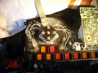
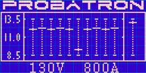
148: Friday 23rd July 2010

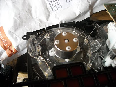
Last weekend I managed to find some time to mount the 9 blue ultra-bright LEDs behind the numbers of the rev counter in my instrument cluster for the instantaneous amps x 100 bargraph display. I also reworked the LEDs in the state-of-charge gauge that I have mounted behind the fuel gauge mask. It now has 4 red, 1 blue, then 5 green indicators. It seems to work o.k. now after a little bit of tweaking. When the indicators are red then the car will be running slower and I need to get it on charge. Now with 10 LEDs I can tell much easier when that time is approaching. It still drops down when I am driving, but when I release the throttle pedal I can get a good reading. I am not going to fix this quirk as when I have my matrix display working, it will just be rough guide. The photo below shows the 9 blue LEDs mounted.
----
The next photo shows the ribbon cable connected. I used the same connector strip as the state-of-charge gauge, so to give it a quick test I swapped them over and the blue LEDs light up nicely. I shall post another photo when I have built up the sensor circuit and bar graph driver for this display. I checked the data sheet for the hall effect current sensor and it needs a 5v regulated power supply, so that is another little circuit I need to build. Progress will be slow but steady now as time and money are at a premium.

147: Thursday 15th July 2010

Yesterday we had the Ford vehicle enthusiasts day at the research and engineering centre where I work. There were lots of cars brought in by the employees and I got an award and trophy for best in the Green class. That was unexpected as I did not know they had a Green class. It was nice to be recognised for the hard work. I have all the LEDs to finish up the instruments, then I can remove the motor controller programming unit. I have some reworking to do for the state of charge display as the bar graph driver is working from the general 12v supply and seems to read a lower level on hot days. I shall rewire this to the constant 6v supply that was originally for the fuel gauge, rework the LEDs to 4 red, 1 blue and 5 green, and recalibrate it to work with the 6v supply. This only involves adjusting the multi-turn potentiometer screw until I get sensible readings. Then I shall build up the Amps gauge. I have made a board layout for the circuit, I need to build the circuit and mount the 9 ultra-bright blue LEDs behind the numbers of the rev counter and then fix the current hall effect sensor on the main battery cable to the motor controller, a little bit of calibrating and that will be ready too. Next job after this is the graphic display and I have a new design now. I have been researching the parts to make this display and have to thank Gordon Stalling for his dialogue and circuits etc. I hope this display will be the next evolution of Gordon's design, but one of the big considerations has been cost and I should have it all built for under £50. It won't look cheap though.