
180: Saturday 26th February 2011
I finally got the Amps x 100 gauge working right. However it only tracks with motor controller programmer test function display when I am in sport mode. I guess this is because the voltage is more chopped in economy mode. Not to worry. I am trying to simplify my controls, so I may start driving in sport mode all the time now. With the gauge I can estimate how economically I am driving. In economy mode the current is limited, so it is hard to drive too hard. This is all very well, but I have to keep flicking over to sport to pull away either that or change gear. I don't want to do either. So I can just be more careful in sport mode and maybe up the regen a bit in sport mode. This does tend to make driving a little more jerky when slowing though. I shall just go up one step on the regen.
179: Tuesday 22nd February 2011
Yesterday I fitted the instruments to the car and went for a test drive. The gauge was way too sensitive and was going all the way round to 8 (800A). I set the car to economy as I knew that it would top out at 500A. I wound the adjustment back on the display circuit and with some trials I got the display to go up to 5 and stop when pulling away in economy mode. Then I put it in sport mode and this also stopped at 5. Clearly this was no good. I wound it out again until I was reading 8, then I realised that the adjustment was just to set how much of the display is used. What I needed was a pre-scalar. I drove it like this today and I estimate I need to trim the signal down by a factor of between 3 and 4. I went to my local electronics store today and bought a multi-turn potentiometer so I can set up a potential divider on the input to the display. Using a multi-turn potentiometer means that by adjusting with a screwdriver, I can get a really fine adjustment. I shall build this onto the display circuit on Friday when I have more time in the daylight. Hopefully then this will work how I expected. I must confess that getting these gauges to work is a bit of a fine art. I shall get there soon be sure. I am looking forward to making some videos soon to show you all the different parts of this project. It is hard to show with just pictures and text.
178: Sunday 20th February 2011
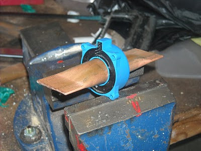
After my initial failure I decided to start by eliminating all the niggly problems in order to get this amps gauge working properly. First I wasn't sure that mounting the current sensor on the cable with its insulation and some plastic tubing to put the cable in the centre of the sensor wasn't losing me some signal. I wasn't expecting the insulation or plastic pipe to affect the magnetic fields picked up, but to be sure I got a piece of 22mm copper pipe flattened one end, pushed the sensor on until it came to a gentle stop, then measured the distance from the end of the pipe to the start of the sensor. It came to 50mm. I measured 50mm from the other side of the sensor along the pipe and cut it there. I then flattened the pipe with care to get the same orientation as the other end. I drilled an 8mm hole in each end to take the mounting bolts. With this mounted on the car, I took some measurements of the output voltage. To do this I had to do something that didn't feel right, but I put my foot hard on the brake and pushed down on the throttle until the motor controller programmer test screen showed 800A (max) and read the voltage from the sensor. It was reading 2.66v. That is only 0.15v higher than the reference voltage of 2.5v. That explains why I was seeing no readings on the display before. So now I knew how the sensor was behaving I had to make another circuit to get that output into a usable form.
 ----
----
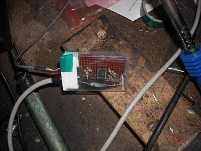
I went to my local electronics shop and stocked up on resistors and transistors. I then set about making an amplifier. My objective was to take the reference voltage and the signal voltage from the sensor and transform them into a single output with respect to 0v and feed this into the display. I would then set up the display to read properly with these new voltages. I built an NPN transistor common emitter amplifier, then another stage to invert the inverted output. I am a bit ropey on my electronics as it was about 25 years ago I first learnt all this. I eventually got to a respectable swing from 3.3v to 4.1v. This was better than the weak signal from the sensor. Next I thought that with this being possible I would try an op amp circuit to see if I could make it simpler and improve the range of the output. Another trip to the electronics store and I had an MC1458 chip that had 2 x 741 op amps on it. After a lot of fiddling about on my proto board, I got a swing from 1.96v to 4.28v. Clearly this was not ideal still. I would have liked to go much closer to 0v for the low level. I did a bit of research and found that because the 741 op amp has a split power supply for positive and negative rails and I was using just 0v and 5v as the supply, then the lowest reading I could get was about 2v (1.96 in my case). Also the highest reading would be 0.7v below the supply voltage and it was. More reading revealed that I should be using a different op amp that was designed for a single rail supply. The photo below shows my proto board with a real junk like circuit on it, but when I fired up the motor and put a load on I was getting some decent voltage levels coming back and they were predictable by design.
 ----
----
Yet another trip to the electronics store got me a LM358 op amp. I read that these are a bit crunchy with respect to their tolerances, but my local electronic store did not have a big choice, so that was it. The LM358 is basically the same as a 741 op amp, but it is designed to work from a single rail power supply and the theory (and their claim) is that the output can go from 0v to the supply voltage. The good thing was that the pin-out was the same as the MC1458, so it swapped out no problem. I found that the range was now swinging from 0.57v to 3.6v. I tried it on the car and at 800A I was seeing 3.41v and at rest 0.58v (there's that drift). Anyway, I could work with that. I took the instrument cluster out of the car with all the new display circuit still mounted. I then added a resistor network to the proto board to set up a 0.5v offset to set the lowest level to detect. I used a 10k resistor in series with a 470 and 220 Ohm resistors making 690 Ohms. This was by trial that I found 0.5v. Now with the adjustment screw I could adjust the top level to detect and then I had my range. I then tested it out and it seemed to work fine. Next step then was to build this up on a vero board, so off to do some circuit layout designs, then build the circuit. After I had finished I mounted the new circuit in a tic-tac box (that a small mint candy box for anybody outside the UK). Tic-tac boxes have been used for many of my smaller circuits as they work on three levels; you get a box to put you circuit in, it doesn't cost much money (cheaper than a small project box), and you gets some mints to enjoy while your doing it. In the photo below you can see the new circuit in it's tic-tac box. So this circuit now sits between the sensor and the input to the "Amps x 100" display and amplifies the signal for the display to show. I tried it out with the gauge all resting on the car and the supply for the display hooked precariously directly to the battery. I ran it to 800A in sport mode (cringe mode - without the car moving) and then in economy mode that I know tops out at 500A and they displayed numbers 0 to 8 and 0 to 5 respectively. Tomorrow I will mount it all back on the car and then go for a drive to check that all is working as expected. This also means that I now have a signal and a 5v supply that I can pick up for my multi display that is next on my list of things to do. Hopefully the display connector will come soon. If it is not here by next week I shall order one from USA and ask my friend Tim to receive it and send it on. The only other 30 pin flat 0.5mm ribbon connector and breakout adapter I could find was in the USA, but although it only cost like $10, they wanted $130 to ship it to the UK. No way.
 ----
----I went to my local electronics shop and stocked up on resistors and transistors. I then set about making an amplifier. My objective was to take the reference voltage and the signal voltage from the sensor and transform them into a single output with respect to 0v and feed this into the display. I would then set up the display to read properly with these new voltages. I built an NPN transistor common emitter amplifier, then another stage to invert the inverted output. I am a bit ropey on my electronics as it was about 25 years ago I first learnt all this. I eventually got to a respectable swing from 3.3v to 4.1v. This was better than the weak signal from the sensor. Next I thought that with this being possible I would try an op amp circuit to see if I could make it simpler and improve the range of the output. Another trip to the electronics store and I had an MC1458 chip that had 2 x 741 op amps on it. After a lot of fiddling about on my proto board, I got a swing from 1.96v to 4.28v. Clearly this was not ideal still. I would have liked to go much closer to 0v for the low level. I did a bit of research and found that because the 741 op amp has a split power supply for positive and negative rails and I was using just 0v and 5v as the supply, then the lowest reading I could get was about 2v (1.96 in my case). Also the highest reading would be 0.7v below the supply voltage and it was. More reading revealed that I should be using a different op amp that was designed for a single rail supply. The photo below shows my proto board with a real junk like circuit on it, but when I fired up the motor and put a load on I was getting some decent voltage levels coming back and they were predictable by design.
 ----
----Yet another trip to the electronics store got me a LM358 op amp. I read that these are a bit crunchy with respect to their tolerances, but my local electronic store did not have a big choice, so that was it. The LM358 is basically the same as a 741 op amp, but it is designed to work from a single rail power supply and the theory (and their claim) is that the output can go from 0v to the supply voltage. The good thing was that the pin-out was the same as the MC1458, so it swapped out no problem. I found that the range was now swinging from 0.57v to 3.6v. I tried it on the car and at 800A I was seeing 3.41v and at rest 0.58v (there's that drift). Anyway, I could work with that. I took the instrument cluster out of the car with all the new display circuit still mounted. I then added a resistor network to the proto board to set up a 0.5v offset to set the lowest level to detect. I used a 10k resistor in series with a 470 and 220 Ohm resistors making 690 Ohms. This was by trial that I found 0.5v. Now with the adjustment screw I could adjust the top level to detect and then I had my range. I then tested it out and it seemed to work fine. Next step then was to build this up on a vero board, so off to do some circuit layout designs, then build the circuit. After I had finished I mounted the new circuit in a tic-tac box (that a small mint candy box for anybody outside the UK). Tic-tac boxes have been used for many of my smaller circuits as they work on three levels; you get a box to put you circuit in, it doesn't cost much money (cheaper than a small project box), and you gets some mints to enjoy while your doing it. In the photo below you can see the new circuit in it's tic-tac box. So this circuit now sits between the sensor and the input to the "Amps x 100" display and amplifies the signal for the display to show. I tried it out with the gauge all resting on the car and the supply for the display hooked precariously directly to the battery. I ran it to 800A in sport mode (cringe mode - without the car moving) and then in economy mode that I know tops out at 500A and they displayed numbers 0 to 8 and 0 to 5 respectively. Tomorrow I will mount it all back on the car and then go for a drive to check that all is working as expected. This also means that I now have a signal and a 5v supply that I can pick up for my multi display that is next on my list of things to do. Hopefully the display connector will come soon. If it is not here by next week I shall order one from USA and ask my friend Tim to receive it and send it on. The only other 30 pin flat 0.5mm ribbon connector and breakout adapter I could find was in the USA, but although it only cost like $10, they wanted $130 to ship it to the UK. No way.

177: Monday 14th February 2011
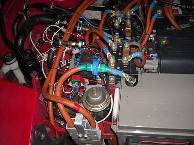
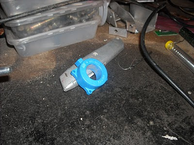
I mounted the sensor on the negative connection using some plastic tubing to make it the right size to fit snug. In the photo below you can see the blue sensor with the sensing wires coming off the side.
 ----
----
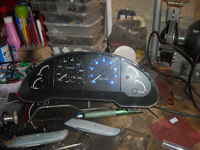
Next was the instrument cluster. I connected this up on the bench and it took 21 photos to get these 2 shots showing the numbers lit up. This is indicating 800A current draw (or it should be when it is on the car).
 ----
----
This is a closer shot. I was seeing loads of glare on the other shots, so I just deleted them. I fitted it all back up in the car and hey presto....... it didn't work! I had my foot on the brake and I eased the power in. I could see the current on my controller programmer tester display, but no change on the gauge. I disconnected the sensor and all 9 LEDs lit up. This was to be expected, so at least I could see the display circuit was working. I tried winding the adjustment screw to both extremes and still there was no display with the sensor connected. I checked the voltages at the connector and there was a problem. The supply was good for 5v at 5.03v, but the reference should be 2.5v and that was 5v and so was the signal sensed. I boxed it up again in the car , but I routed the wires so that I only needed to remove the panel by my feet to get to the circuit and all the connections. Tomorrow I shall investigate what is going on with the sensor side. The only other thing I could think of was that the wire insulation and the plastic pipe were blocking the magnetic fields? I shall get the right voltages first then I might change the mount to 22mm copper pipe and put it in the power circuit to get better sensing.
 ----
----Next was the instrument cluster. I connected this up on the bench and it took 21 photos to get these 2 shots showing the numbers lit up. This is indicating 800A current draw (or it should be when it is on the car).
 ----
----This is a closer shot. I was seeing loads of glare on the other shots, so I just deleted them. I fitted it all back up in the car and hey presto....... it didn't work! I had my foot on the brake and I eased the power in. I could see the current on my controller programmer tester display, but no change on the gauge. I disconnected the sensor and all 9 LEDs lit up. This was to be expected, so at least I could see the display circuit was working. I tried winding the adjustment screw to both extremes and still there was no display with the sensor connected. I checked the voltages at the connector and there was a problem. The supply was good for 5v at 5.03v, but the reference should be 2.5v and that was 5v and so was the signal sensed. I boxed it up again in the car , but I routed the wires so that I only needed to remove the panel by my feet to get to the circuit and all the connections. Tomorrow I shall investigate what is going on with the sensor side. The only other thing I could think of was that the wire insulation and the plastic pipe were blocking the magnetic fields? I shall get the right voltages first then I might change the mount to 22mm copper pipe and put it in the power circuit to get better sensing.

176: Sunday 13th February 2011
The circuit for the Amps x 100 gauge is finally built. I had a few problems along the way, but got round them. I didn't realise the current sensor output voltage was with respect to the current sensor 2.5v reference. I had to remove the ground to the low end reference voltage and apply the 2.5v reference. Using the calculations on the current sensor data sheet the maximum current reading would produce an output voltage of 4.375v and that is 1.875v above the 2.5v reference. With no current being sensed, the output voltage is 2.5v. I also worked out that I should see about 3.67v when the current is about 500A. I calibrated the display driver by feeding 2.5v in the reference, 4.375v in the input connection and then adjusting the multi-turn pot until 9 LEDs were lit on the temporary display. I shall change the connector strip on the gauge ribbon cable as I am using a different type now and the old one will just fall straight out. The new connector strips are much more secure. Once I have it set up on the bench I can illuminate the ultra bright blue LEDs on the instruments so I can get some photos. It would be difficult to do this once I have fitted it on the Probatron as I would need to pull current and that would require me to be driving and taking photos at the same time. Even if I get someone else to take the photos then they would only be vague as they would need to be done over my shoulder as I am driving. If I do this on the bench then I can get a much better shot without any stress. I had to add a 5v supply regulator to the circuit to supply the sensor and I had not planned for this on my board layout design, but I did leave some extra strips all the way round and I could mount this on them, just had to add a link and put one track break on the back of the vero board and that was working fine. I am looking forward to fitting this tomorrow when I get home from work. I have been putting this job off since before Christmas. I hope then to get the matrix display built. I have been discussing this with Tim Catellier ( http://evz3.blogspot.com/ ) and I have decided that when I design the display I want to build an algorithm into the PIC chip to keep adding the accumulated current draw and keep a record of the Amp hours used. I can then over time see how the battery pack is performing. Since the Amp hours is a proper measure of the battery capacity, being able to measure this should tell me more accurately when I am all done and to find a charger. In case you are wondering, the box is just a DV tape box with some insulation tape wrapped round to keep is shut. Notice the hole I drilled very carefully where the adjustment screw is, so I can now leave it "sealed up" and still adjust it. The last gauge I made had to be adjusted with the lid off the project box I had it in. This is much better. Also if I mount this box so that it can be accessed without having to remove the instruments each time I want to "tweak" it then that would be just great.

175: Saturday 12th February 2011
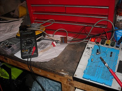
I have been putting off working on the Probatron until I had tidied up my garage a bit. Today I set out to get my bench organised. I took my arc welder off and got rid of a load of rubbish, put some tools away and generally moved stuff around so I could work in comfort. That took me a good few hours. Then I got stuck in to building the display driver for the Amps x 100 bar graph display. You may remember from post 148: Friday 23rd July 2010, that I have mounted ultra bright blue LEDs behind each of the numbers around the rev counter (tacho). These are wired up to a ribbon cable ready for connection to the driver circuit that I have now made. The photo shows the circuit connected up on the bench with a temporary display for bench testing.
 ----
----
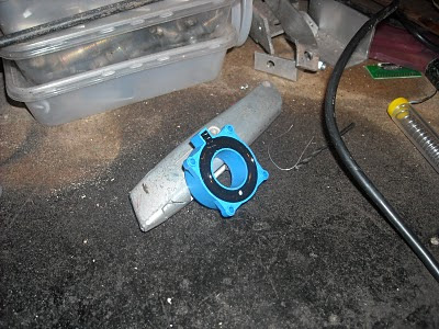
You may wonder how the current is going to be sensed? The device in the photo below is a hall effect current sensor and it measures the magnetic field surrounding a current carrying conductor (the power cable). This device takes nothing away from power source as it is an active measuring device to measure a magnetic field, not current directly like a shunt does. However even a shunt does not measure current directly as the shunt gives its meter a voltage across it depending on the current through it. This is achieved by applying a small load through a small resistance. This does not take much from the batteries, but it does cost about £50 for a shunt resistor and £10 for a hall effect sensor. The magnetic field is directly proportional to the current therefore once the display is calibrated, it should stay accurate. This is the back view. If you enlarge this photo you will see the connections at the top.
 ----
----
The next photo is just the front view of the same sensor. As you can see all you need to do is disconnect the battery negative and pass it through the centre of this sensor. The sensor itself needs a steady 5v supply and is supposed to give out a signal that is a dc voltage up to 5v when 800A is being pulled, and proportionally less down to 0v when no current is being drawn.
 ----
----
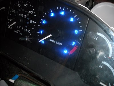
The photo below is a close up of the driver circuit and the temporary display. I have my voltage meter hooked up to the signal into the circuit and it was reading 2.5 volts. This you can see this lights up 5 LEDs (the numbers 0 to 4 on the tacho) and this will then indicate half the maximum i.e. 400A. The gauge is therefore displaying Amps x 100. Just like the tacho displays revs x 1000. It was convenient that my tacho happened to go up to 8. Also you can see the blue trimmer pot on the circuit board. This is a multi-turn pot that can be adjusted in very small increments to set the bar graph to correspond to the current being drawn. This is simply adjusted with a jewellers screwdriver using the screw on the top. You may need to enlarge the photo to see this properly. I have circuit diagrams and board layouts for vero-board if anybody is interested.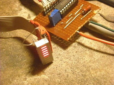
 ----
----You may wonder how the current is going to be sensed? The device in the photo below is a hall effect current sensor and it measures the magnetic field surrounding a current carrying conductor (the power cable). This device takes nothing away from power source as it is an active measuring device to measure a magnetic field, not current directly like a shunt does. However even a shunt does not measure current directly as the shunt gives its meter a voltage across it depending on the current through it. This is achieved by applying a small load through a small resistance. This does not take much from the batteries, but it does cost about £50 for a shunt resistor and £10 for a hall effect sensor. The magnetic field is directly proportional to the current therefore once the display is calibrated, it should stay accurate. This is the back view. If you enlarge this photo you will see the connections at the top.
 ----
----The next photo is just the front view of the same sensor. As you can see all you need to do is disconnect the battery negative and pass it through the centre of this sensor. The sensor itself needs a steady 5v supply and is supposed to give out a signal that is a dc voltage up to 5v when 800A is being pulled, and proportionally less down to 0v when no current is being drawn.
----The photo below is a close up of the driver circuit and the temporary display. I have my voltage meter hooked up to the signal into the circuit and it was reading 2.5 volts. This you can see this lights up 5 LEDs (the numbers 0 to 4 on the tacho) and this will then indicate half the maximum i.e. 400A. The gauge is therefore displaying Amps x 100. Just like the tacho displays revs x 1000. It was convenient that my tacho happened to go up to 8. Also you can see the blue trimmer pot on the circuit board. This is a multi-turn pot that can be adjusted in very small increments to set the bar graph to correspond to the current being drawn. This is simply adjusted with a jewellers screwdriver using the screw on the top. You may need to enlarge the photo to see this properly. I have circuit diagrams and board layouts for vero-board if anybody is interested.

Subscribe to:
Posts (Atom)