145: Saturday 29th May 2010
Today I went back to the electrical wholesaler and got the correct circuit breaker for my fuse board. I fitted it and run the cable through the garage to the new 16A socket just out side my garage door. I now have a dedicated charging point and no more blowing fuses. My wife was asleep, so I told the dogs (Sasha and Merlin) but they didn't care much. See the photo below for the charge point.


144: Friday 28th May 2010
If you work at Ford in the UK, see if you can still get hold of a copy of the May Ford news. If you click on the article below, you can read it properly.
 ----
----
After a succession of blown fuses, I decided it was time to uprate the protection for the charger. It was blowing a 13A fuse about once every week or two, so it must be just borderline. The last time I noticed the plug on my extension lead, the plastic on the live pin had gone all crispy and it fell apart in my hand. I put a new plug on it and moved it to another socket. I bought the parts to wire a 16A socket to my fuse board, but I got the wrong type of circuit breaker for the fuse board that I have. I still had the right parts for the car, so I set about fitting those. You can see in the photo below there is a circuit breaker in the box that mounted on the bracket where the cruise control module used to sit. I removed the cruise control module and the cable (that was always in the way), and mounted the new circuit breaker. It is now rated to 16A just like the caravan type connector. I shall pop down the electrical wholesalers tomorrow morning before my daughter's football training and get the other circuit breaker changed for the right type. I am using a 20A breaker in the fuse board to ensure that it will trip on the car first unless there is a problem with the cable getting cut then it will trip on the fuse board.
After a succession of blown fuses, I decided it was time to uprate the protection for the charger. It was blowing a 13A fuse about once every week or two, so it must be just borderline. The last time I noticed the plug on my extension lead, the plastic on the live pin had gone all crispy and it fell apart in my hand. I put a new plug on it and moved it to another socket. I bought the parts to wire a 16A socket to my fuse board, but I got the wrong type of circuit breaker for the fuse board that I have. I still had the right parts for the car, so I set about fitting those. You can see in the photo below there is a circuit breaker in the box that mounted on the bracket where the cruise control module used to sit. I removed the cruise control module and the cable (that was always in the way), and mounted the new circuit breaker. It is now rated to 16A just like the caravan type connector. I shall pop down the electrical wholesalers tomorrow morning before my daughter's football training and get the other circuit breaker changed for the right type. I am using a 20A breaker in the fuse board to ensure that it will trip on the car first unless there is a problem with the cable getting cut then it will trip on the fuse board.
143: Thursday 6th May 2010
You may remember I had mentioned that the mileage counter was not working and I now know how important this is. I had a disaster on the way to work. My wife had asked me to drop off some paperwork on my way in, so I set out with the paperwork and arrived at work and it was still on the passenger seat, damn! I had gone to work in sport mode as it is only 7 miles and this is easy, but now I had to go part way back and return to work. Without the mileage counter I had no idea how far I had gone and I thought it was only an extra 2 miles, but it turned out to be about 11 miles extra round trip. I got within 1 mile of my work and could go no further without going really slow and damaging the batteries. So I had to get a tow for the last mile. I did stick it in 5th gear and let the regen charging put some back while I was being towed. I had to wait about 30 minutes for rescue and ended up about an hour late for work. I had originally arrived early. I now appreciate how important the mileage indicator is and when I got home from work I set about fixing the counter. I stripped the instrument cluster out of the car and took the counter mechanism apart. When I was drilling the holes for the LEDs on the back of the fuel gauge markings, a tiny piece of the plastic swarf had gone in the cogs and jammed them. I gave it a quick blow, put it back together and it is all working again now. No more range anxiety! Next job is to build a bar graph driver circuit for the 'motor amps' meter LEDs, get the LEDS and mount them. Until then I have the rectangular LED bar graph matrix that I used for the temporary fuel gauge to get started with.
142: Wednesday 5th May 2010
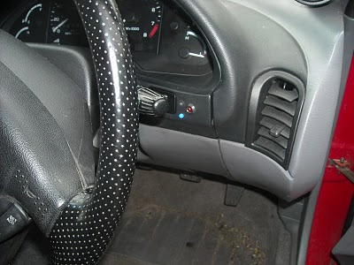
I finished up the charge indicator LEDs. When I was trying to find a supply for the connection to the common terminals on the 120v battery charger, I picked up a 12v supply from the diagnostic connector. While I was making the connections, the other end of the wire touched a screw head and the horn went off continuously. So I got a piggy-back connector on the fuse block for the control box and looped across to a spare fuse slot instead and fitted a 5A fuse in it. Then I picked up the other side of the fuse to the common terminals. I wired the normally open contacts for aux1 and aux2 on the charger to the LEDs. I had already installed 1k drop resistors at the LED ends. Now when I plug the charger in the bottom blue LED comes on (see photo), and when the charge is complete both LEDs come on. If the fuse in the mains supply blows or the supply is interrupted for any other reason then all the LEDs are off, simple!

141: Tuesday 4th May 2010
Today I intended on getting my charge indicators working, but the distraction was that one of my external hard drives wouldn't work on my PC, so I spent ages trying to fix it to no avail. I did get the 2 x 5mm blue LEDs mounted on the cluster bezel with the cable and a 3 pin connector on the end. Small progress! Tomorrow I will try and get the wires through to the charger so I can connect it all up. One indicator shows that the mains electric supply is connected and the other shows when the charge is complete. As I have blown a few fuses it will be useful to see when the mains has gone off. While the car is charging, if you listen carefully you can just about hear the fans in the charger. But without opening the hood I have no way of knowing it has completed until now (well maybe tomorrow).
140: Sunday 2nd May
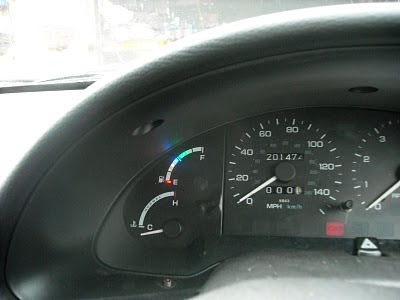
Didn't really do anything today as I was supposed to limit my car projects to weekdays. I was also supposed to be building a brick wall, but it rained nearly all day. I did go for a little drive (providing the Dad taxi service) and the gauge is working fine, and I took some more photos. This time they came out much better due to the day light. The first photo is more like what you see at night and the second like daytime. You can see how weak the yellow and orange LEDs are in these shots. I will be swapping these for red ones and adding 2 more green to the top end of the scale. For some reason the mileage counters have stopped working. It is probably where I took the cluster apart. The speedo still works fine, but I can't tell how far I have gone. It is a good job that I now have a battery level indicator so I know when to go on charge. It still looks much clearer in real life than in the photos.

139: Saturday 1st May 2010
I have now completed 1000 miles of electric driving and it has been relatively trouble free.
----
I left the newly glued LEDs to set overnight and then joined all the anodes together with solder. I had soldered a strip of pins onto one end of a ribbon cable that I salvaged from my "computer bits" draw and then stripped the other ends and soldered them to each LED cathode and one wire to the joined up anodes. I then plugged the pin strip into my prototype board, applied the correct resistance and checked they all worked. The orange and yellow ones didn't appear as bright as the red, blue and green. Next I took the LED matrix display off the circuit board and mounted a strip of pin sockets in its place for the ribbon cable to connect to. I gave the circuit a quick test using a potentiometer to provide the input voltage and it worked fine as a curved bar graph on the fuel gauge. Next I put some black tape over the hole where the needle broke off the fuel gauge from when I dropped it. I put insulation tape round the legs of the LEDs and mounted the gauge back into the instrument cluster.
 ----
----
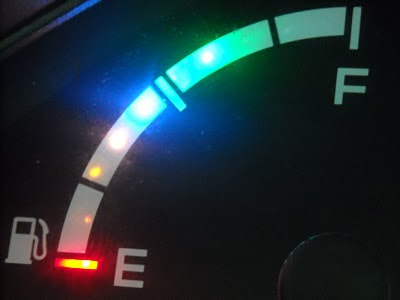
I then mounted the cluster back in the car and connected the circuit. A quick test, then I put the rest of the trim back together. In the photo below you can get an idea of how the gauge will look at night. The photo was really difficult to take as in real life you can see definite dots where the LEDs are. All the LEDs look like the top one in the photo.
 ----
----
If you click on the photo below you can see what it looked like when I used flash on the camera. This gives and idea about how it would look in daylight, but once again in reality it is a lot clearer than in the photo and perfectly acceptable for normal driving. I am not entirely happy with the orange and yellow LEDs, so I am going to swap them for red when I add the other 2 green LEDs. I am keeping the blue because after a quick drive from a half flat battery pack I found that when the blue LED goes out it starts getting a bit sluggish and really needs to go back on charge. I checked the tester on the programmer and this was at about 119v, so that rings true.
So after several weeks experimenting I now have a separate "state of charge" gauge that shows when I lift off the throttle. This is a quirk I am prepared to suffer. I might come back to this at a later date as I am planning a battery monitor for each of the 10 batteries using a text display showing a bar graph for each battery, then I could use the PIC chip to sample the overall voltage when the throttle is released, keep the display showing this level and update it when the throttle is released again, so the gauge will show a steady display. I will consider this a future upgrade. Next is the Ammeter. I just need to order 10 ultra bright 5mm blue LEDs for this then I have all the bits to get it working. I think I will make a start and have the matrix display that I used before until I get the proper LEDs. This time I will have it hanging down by the cluster as hanging out of the air vent was not easy to see.
----
I left the newly glued LEDs to set overnight and then joined all the anodes together with solder. I had soldered a strip of pins onto one end of a ribbon cable that I salvaged from my "computer bits" draw and then stripped the other ends and soldered them to each LED cathode and one wire to the joined up anodes. I then plugged the pin strip into my prototype board, applied the correct resistance and checked they all worked. The orange and yellow ones didn't appear as bright as the red, blue and green. Next I took the LED matrix display off the circuit board and mounted a strip of pin sockets in its place for the ribbon cable to connect to. I gave the circuit a quick test using a potentiometer to provide the input voltage and it worked fine as a curved bar graph on the fuel gauge. Next I put some black tape over the hole where the needle broke off the fuel gauge from when I dropped it. I put insulation tape round the legs of the LEDs and mounted the gauge back into the instrument cluster.
 ----
----I then mounted the cluster back in the car and connected the circuit. A quick test, then I put the rest of the trim back together. In the photo below you can get an idea of how the gauge will look at night. The photo was really difficult to take as in real life you can see definite dots where the LEDs are. All the LEDs look like the top one in the photo.
 ----
----If you click on the photo below you can see what it looked like when I used flash on the camera. This gives and idea about how it would look in daylight, but once again in reality it is a lot clearer than in the photo and perfectly acceptable for normal driving. I am not entirely happy with the orange and yellow LEDs, so I am going to swap them for red when I add the other 2 green LEDs. I am keeping the blue because after a quick drive from a half flat battery pack I found that when the blue LED goes out it starts getting a bit sluggish and really needs to go back on charge. I checked the tester on the programmer and this was at about 119v, so that rings true.
So after several weeks experimenting I now have a separate "state of charge" gauge that shows when I lift off the throttle. This is a quirk I am prepared to suffer. I might come back to this at a later date as I am planning a battery monitor for each of the 10 batteries using a text display showing a bar graph for each battery, then I could use the PIC chip to sample the overall voltage when the throttle is released, keep the display showing this level and update it when the throttle is released again, so the gauge will show a steady display. I will consider this a future upgrade. Next is the Ammeter. I just need to order 10 ultra bright 5mm blue LEDs for this then I have all the bits to get it working. I think I will make a start and have the matrix display that I used before until I get the proper LEDs. This time I will have it hanging down by the cluster as hanging out of the air vent was not easy to see.
138: Friday 30th April 2010
I got home from work and stripped the instrument cluster from the Probatron. I had 10 x 5mm blue LEDs and was planning to mount them behind the mask for the rev counter to show the instantaneous Amps (x100). I had been to the electronics store on my way home and asked what they had for 3mm red, yellow and green LEDs, but someone had been in and bought just about all of their stock. So with the task of lighting up the ammeter in hand, I drilled the holes in the plastic behind the mask in line with the numbers on the dial. I put a 5mm blue LED in my prototype board to light it and held the dial over it. I found that didn't shine through as bright, so I went back to the electronics store to get ultra bright LEDs. They didn't have any ultra bright 5mm blue LEDs, so I came away with 3mm ultra bright LEDs in the following colours; 1 x red, 2 x orange, 2 x yellow and 5 x green, making 10 in total, all for the fuel gauge conversion. In the photo below you can see the holes drilled in the plastic behind the fuel gauge mask. I had drawn the blue line where the stripe was and by the application of trigonometry I worked out how far apart they needed to be around the circumference and using my vernier calipers I put scratch marks where I needed to drill.
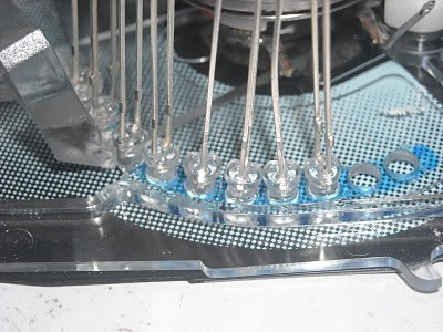
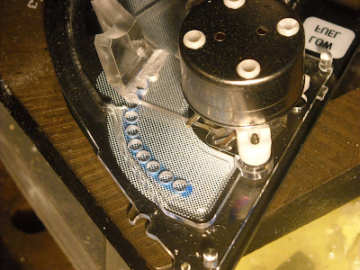 I then set about mounting the LEDs in the holes. I tested each one before fitting it to be sure. In the first hole went the red LED, then the first orange, but the next hole was by thinner plastic, so when I put the super glue on, it kept falling over. I went to get my pliers so I put a sticky foam pad on the legs of the other LEDs to hold this one, I got the LED legs in my pliers and went to put it in then dropped it on the floor. After 20 minutes on my hands and knees sifting through swarf an dust and scraps of wire and metal etc. I abandoned my search and decided to proceed with 9 LEDs. I put the 2 yellow LEDs in with great care. When it came to the 5 green LEDs I thought I would test them all first, wise move! I found one was blue and one did not work at all. So I decided to mount the blue one next followed by 3 greens. In the photo below, you can see all the LEDs mounted and 2 spare holes that I will come back to another day. I was happyish to settle for 8 LEDs for now. It was better then having a project box hanging out of my air vent. So now I can't tell when it is fully charged properly, but I am more interested in when it is getting low than when it is full right up. My super glue was past its sell by date, so it took a while to set. It would have been a lot easier with fresh super glue. In case of global understanding, super glue is cyanoacrylate glue. I know there are several names for this, but in the UK it is best known as super glue.
 I then set about mounting the LEDs in the holes. I tested each one before fitting it to be sure. In the first hole went the red LED, then the first orange, but the next hole was by thinner plastic, so when I put the super glue on, it kept falling over. I went to get my pliers so I put a sticky foam pad on the legs of the other LEDs to hold this one, I got the LED legs in my pliers and went to put it in then dropped it on the floor. After 20 minutes on my hands and knees sifting through swarf an dust and scraps of wire and metal etc. I abandoned my search and decided to proceed with 9 LEDs. I put the 2 yellow LEDs in with great care. When it came to the 5 green LEDs I thought I would test them all first, wise move! I found one was blue and one did not work at all. So I decided to mount the blue one next followed by 3 greens. In the photo below, you can see all the LEDs mounted and 2 spare holes that I will come back to another day. I was happyish to settle for 8 LEDs for now. It was better then having a project box hanging out of my air vent. So now I can't tell when it is fully charged properly, but I am more interested in when it is getting low than when it is full right up. My super glue was past its sell by date, so it took a while to set. It would have been a lot easier with fresh super glue. In case of global understanding, super glue is cyanoacrylate glue. I know there are several names for this, but in the UK it is best known as super glue.
Subscribe to:
Posts (Atom)


