95: Thursday 31st December 2009

I took a day off yesterday as I was feeling quite ill. I still have a touch of the sniffles, but not so bad today. At least I rested all the aches that have been developing over the last couple of weeks. Today I connected up the Anderson connector and put the caps on the batteries. I then run the cables through to the trunk. I decided to go inside the car and under the trim. This means the cables are protected from the elements and it all looks nice and tidy (invisible in fact).
----
I ran the 2 cables for the batteries and a cable for the charger to connect to the plug at the fuel flap. You can see in the photo that these come into the car behind the glove box. I have pulled them over to the side where they will sit behind the front side trim. I tried to push the cables in along the side of the door, but I am going to need to do some special routing as this clashes with the seat belt anchor point. Everything else is o.k. Once I get the cables hidden past the door then the back quarter is easy.
----
I left the battery cable in a loop for the time being until I have the batteries mounted, then I can make the cuts to the correct length. Once I have the cable routed, then I can make up the battery mounting brackets. Not too much else to do now. Oh I still have to take off the fuel tank....!

94: Tuesday 29th December 2009

No real distractions today, except that it was raining all day. I fashioned a shelter from the outer cover of my old gazebo between the garage door and the car hood. The cardboard is to stop it sinking and getting a pool build up. With a dry (and very cold) working environment I could start.
----
I mounted the DC-DC converter onto the battery hold down bracket. I had to make an aluminium bracket to do this so it is nice and secure and doesn't rattle. I need to re-wire the 12v side at some point, but I did not have enough heavy duty cable to do it today, so I used what I had left over from the charger. I also connected up the 12v side of the charger to the contactors, where the battery supply connects.
----
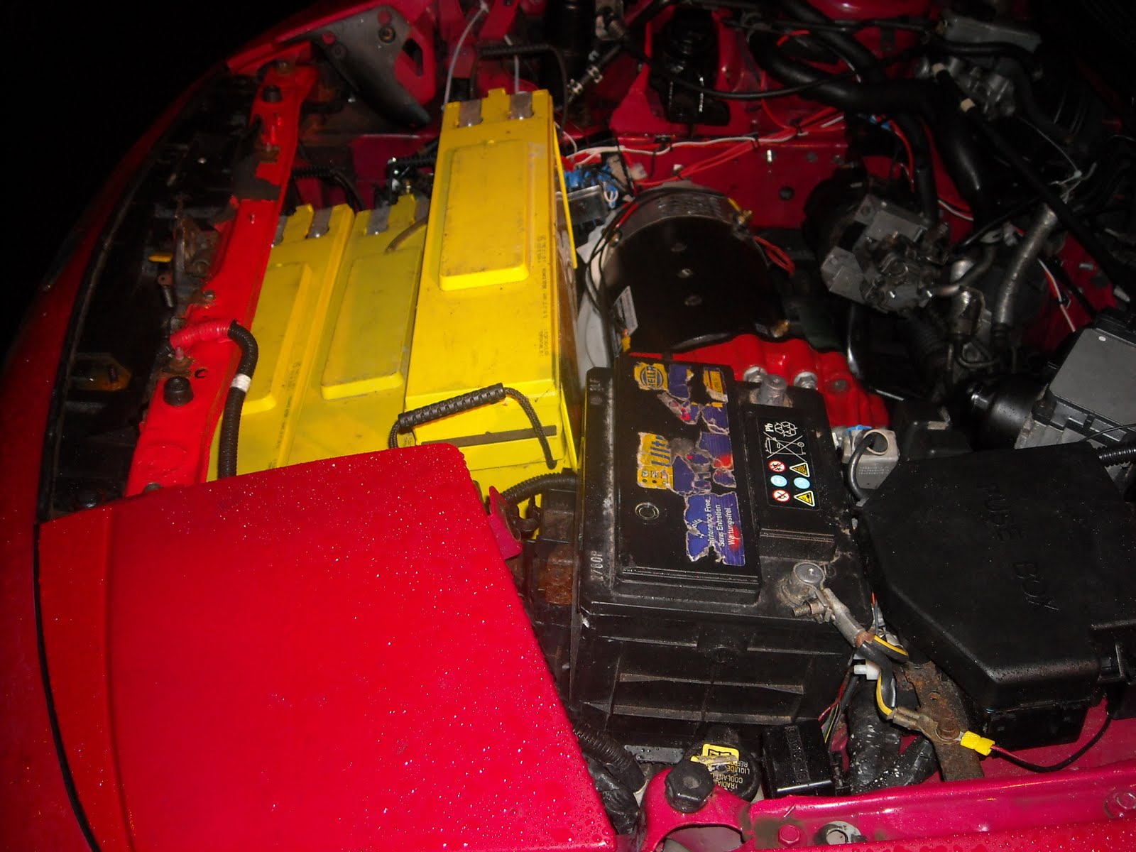
I also found a home for the Anderson connectors. I mounted them onto the side of the add-on bracket that I made for the vacuum pump. Of course nothing is so straight forward, initially the location would have clashed with the vacuum pipe, so before I could mount the connectors I had to re-route the vacuum pipes. Fortunately one of the pipes had a nice sharp right angle on it, so that made things simpler. I used riv nuts on the steel angle iron. I found that if I drilled the hole for the riv nut, then drilled into the back with a much bigger drill, but not right through, then the riv nut could spread into the space the bigger drill created. This made it very easy to mount the connectors and as the riv nuts have a small flanged edge, this spaced the connector off of the angle iron. I guess it is about the same as slipping a washer in, but much easier. No fiddly nuts to play with here. I also mounted the three batteries in the front and connected them together. So I am now up to 36v, only another 84v to go. It started getting colder and the rain was coming across so the shelter was only just about keeping everything dry, so I called it a day. I shall make the power connections between the Anderson connector and the contactors tomorrow, then I can move to the back of the car and running the power cables along the underside. Oh and removing the fuel tank of course.

93: Monday 28th December 2009

Today's distraction was switching my lounge from left to right. I had to re-route all the cables etc. for my surround sound, network for my customized XBox (Mk1), cable TV, speakers, sub woofer, then move all the furniture..... It took about 6 hrs all in. Our new corner suite looks much better on the other side though.

I managed to slip out to my car and hook up the minus 120v connection for the heater. Unfortunately I thought I might be able to get this from underneath, but it was not to be. I had to take out the charger, disconnect most of the controller connections, so that I could reach down behind it to make one connection for the heater and route the cable to where the contactors are. It took about an hour to strip it down and put it back together again.

92: Sunday 27th December 2009

Today's distraction was a trip to the dump to get rid of the Christmas cardboard boxes and wrapping followed by a trip to the town to drop off my daughter. All that took just over an hour, so not so bad. One of those niggle jobs, I fitted the temperature sensor that I made into the motor. I put heat conducting grease on the threads and at the end of the bolt so there will be optimum performance from the sensor. You may remember that this hooks up to the old coolant temperature gauge in the original instruments and has about the same temperature range as engine coolant. Now that is done I moved on to the controller 120v connections and the pot box etc.
----
The cable I had on the throttle pot box was way too long and the grommet into the box had dissolved. So I cut the cable fitted a new grommet and seated it and and re-made the the connections to the controller. Next was the battery discharge indicator cable. This was too short to reach the motor controller, so I cut the connection and made new ends and soldered these to the old end. I used rubber sleeves to cover the solder joints, then taped the whole lot up. A similar procedure was required to extend the connection for the contactors that I separated by cutting the plate for a better mounting position. Then I moved on to the connections between the control box on the 120v side to the motor controller including; the throttle micro-switch, the forward and reverse controls and the line contactor. I need to run a cable for minus 120v for the heater to the battery minus connection then that is nearly all done for the 120v side. Next big job is installing and connecting the batteries, the charger and the DC-DC converter. Oh and I still need to take the fuel tank out. Then I can fix the power connector in the fuel flap.

91: Wednesday 23rd December 2009

Today's distraction was helping my wife with her newspaper distribution job. I didn't get anything done on the Probatron as the truck didn't deliver until just before noon and with all the ice on the ground everything took twice as long walking carefully and all. No more work now until after Boxing day when I have a few days with no plans....Cool. Merry Christmas to all. I am looking forward to getting rid of my gas!

90: Tuesday 22nd December 2009

Today's distraction was planned as in the afternoon we were setting off on a train to London to go to the Imax cinema to watch Avatar in 3D. It was a really cool film. At the end of the film the ...... I am not that cruel, see it for yourself and find out what happens at the end. With limited time I set out to mount the throttle cable to the throttle pot box. I first made up the bracket from aluminium L section and mounted the pot box and cable to it. Then I had to find a home for it. The problems were numerous and I now empathise with Packaging Engineers in the auto trade; the cable could not bend too much or it would foul and jam, there needed to be something to fix to that could be accessed with tools and it could not be touching any cables or moving parts. I tried beside the vacuum pump, down by the PAS pump, and I found the perfect place on the firewall, but I would have to cover the VIN plate and that is not allowed. I ended up in the space between the motor controller and the Zivan 120v charger, but this had nothing to mount to apart from the plastic cases of these two devices. I made some additional brackets from aluminium bar to support the throttle bracket. It did not need to be strong as the cable pulling was already accounted for on the throttle bracket. So these two new brackets bolted to the motor controller plate and hold it nicely. There is a couple of millimetres of clearance around the brackets and it does not touch and of the moving cables and other parts. There are 3 photos below to try to show the different brackets from different angles. Otherwise it is a bit difficult to see as the throttle is mounted in a gap.


89: Monday 21st December 2009

Today's distractions, a trip to the town to go to the post office to pick up a Christmas card that someone had forgotten to put a stamp on, cost me £1.30 too, pick up some paperwork from my wife's work office, then onto the supermarket for food shopping. Somehow that took 4 hours out of the day. So I came back ready to get stuck in and it fell down with rain. Before we went out I did manage to put the newly painted brackets back together.
----
I then put the controller and charger on the brackets and found that I couldn't access one of the bolts for the contactor plate and the motor connections. I took the charger back off and fitted the contactor plate to the frame, then wired up the field connections of the motor to the controller. Fortunately some of the cables I made for my earlier experiment with the controller and motor were perfect for what I was connecting now. Where I had taped the ends, I now put heat shrink to cover the ends of the cables. It was easy, in fact the hardest part was finding my instant heat gun. A quick blast of heat onto the heat shrink and the ends look perfect now.
----
I fashioned a rain cover going between my garage door and the car hood so I could carry on in the rain. I used the old bracket that I made for the vacuum pump to mount the 12v control box onto the same mounts as the vacuum pump. I was able to use the same holes, so that was a quick job to fix it all together. I then finished up making the connections for the motor, controller and the contactors. Next job is the throttle box.

88: Sunday 20th December 2009

Today's distraction was a trip to the town for some Christmas shopping, but I did manage to pick a pack of longer bolts. Just as well that I got some more bolts as I am going through them like they are going out of fashion. It takes 8 bolts and 4 nuts (I used riv nuts on the brackets) to mount the motor controller, and the same to mount the charger. It took another 4 nuts and bolts to mount the motor contactors. That's 20 bolts and 12 nuts! You can see in the photo below that I have made up the mounts for the Zivan 120v charger so that is now ready to mount. I also added the bracket to the left side of the motor and charger brackets to support the contactors. I drilled the contactor plate and the brackets and checked the whole lot all bolted in place.
----
Then I had to take it all apart to give it the customary coat of red paint. It is not just cosmetic, I chose red Hammerite as it provides a good barrier to rust (it says 5 year guarantee on the tin) and it matches the colour of the car. I also prepared the throttle box linkage so it can take the end of the cable and worked out the brackets to mount the control box for all the 12v controlled devices. There's them dogs again....

87: Saturday 19th December 2009

Well yesterday we organised a Santa's grotto and some of the local kids came and received prezzies and put a decoration on the Christmas tree on the green.
----
You can see from the photo below that the weather has not been too good (freezing cold). I am still pressing on.
----
Today is panto day, so didn't have much time to work on my car. I got the aluminium brackets made up to fix the motor controller in place. I didn't have much metal around the controller to drill through, so I need to make some collars to support the bolts as they clash with the controller itself on 2 of the fixings. Of course this will also need to be painted red. The aluminium brackets were thin enough to take riv nuts so that makes it easier to fix the controller to the brackets as space is limited.

86: Friday 18th December 2009

Today is my birthday and for those of you that work with computer code, I am 0x2B years old or b101011. My daughter got me some stick on letters for the finishing touches when I have the car running. She wrapped every one separately (ahh bless her). I laid them out on a folder. A pleasant job to do soon.
----
I mounted the vacuum pump with its freshly painted bracket, so that is now ready, just need to get a new vacuum switch and connect it all up again.
----
I also re-made the bracket for the PAS pump again (4th time lucky). I just re-drilled the mounting holes another 1/2 inch over to separate the pump from the motor a bit more. Should have enough clearance between the intermediate shaft bearing bracket and the PAS motor mounting. The motor will twisted at this point when a load is applied, so this should clear no problem.

85: Thursday 17th December 2009

Mounted the painted battery support frame today. I put a fresh coat of paint on the bits you will see most and touched up the gearbox a bit where some paint had chipped off and also on the slam panel.
----
made a new bracket from angle iron that goes between the battery frame and the body to support the vacuum pump in the correct horizontal orientation. I also changed back to the anti-vibration mounts that came with the pump. Now I have all the manufacturers mounts and it is mounted as they recommend, so there should be very little noise evident inside the car when the pump is running. I must contact Erick in China to get the replacement vacuum switch. The old one that I sent back seems to have got lost in the post, so he said I would need to pay postage for a new one. Not his fault I suppose, and probably cheaper and quicker than getting it from the u.k. Not too much today as it is freezing cold here. I took the bracket in the garage and gave it a coat of that red paint and called it a day.

84: Wednesday 16th December 2009

Finished painting the other half of the battery supports (more of that "fire truck" red) and mounted the intermediate shaft bearing support bracket. In the photo I have circled the bearing as the photo is a bit dark.
----
I also made up a blanking plate from aluminium to cover the hole where the starter motor used to fix onto the gearbox. That's another little job out the way. I shall mount the first 3 batteries tomorrow, then start fixing the controller etc. in place.


83: Tuesday 15th December 2009

Decided to have a break yesterday night as I was hard at it all weekend. So just a lot of painting tonight. Red Hammerite, my favourite! I could only do half of the battery support as it was too big to get round all of it and hang it up, so I shall flip it over tomorrow then paint the other side. Then I need to mount the controller etc. again and secure it this time. I also painted the battery hold down bracket and the intermediate shaft bearing support bracket. Check out the calendar hanging up next to the brackets. The little dog looks just like my Sasha.

82: Sunday 13th December 2009

Spent nearly all day welding. Anyway, you can see from the photo below that the battery supports are now fabricated. Remember the wooden model and you can see the metal version now. It is slightly different, but then I wasn't using wooden angle iron, so what do you expect! I then went on to making the bearing support for the intermediate shaft. I forgot to take a photo of this though. It was very fiddly to fix together and mount as access for a spanner behind the angle iron was limited. I had a brainwave and welded the nuts on the back of the angle iron, now just slip the bolts in and it is easy. This bracket start at the gearbox bolt, meets the bearing support half way along, then a plate around the corner joins onto the motor mount bolt. It was absolutely rigid when secured, so no worries there. I gave the motor a little run with a single 12v battery just to ensure everything still ran nice and smooth and produced no weird noises. All o.k. there as well.

81: Saturday 12th December 2009

Unfortunately my wife and daughter were both ill with flu or a cold. Fortunately this meant no football training, so another full day, yippee! When I phoned up my daughter's football club they told me there was no match planned for tomorrow, double yippee!! I carefully measured and marked each piece then took it in the garage and welded it together. The photo shows the completed battery hold down strap. I used a riv nut to fix the strap to the slam panel (I love riv nuts!).
----
Next up was to weld the battery supports together, then I can take all the bolts out that were holding it together during construction. The one in the photo was still hot, so I left the bolts in for now.
----
With all the supports welded together it was time to try it all out again. Everything fits, snug, but it fits. The photo shows everything in place. Next job is to weld the supports to the cross brace and fit the riv nuts at the front to fix the brackets to, then fix the other parts to the brackets that I made before. I have decided to relocate the vacuum pump as it is not mounted in the correct orientation at the moment. Oh and I need to get my vacuum switch back otherwise the vacuum pump won't work. I need to make up brackets to hold the seven batteries in the trunk, then it is time to wire it all up.

80: Friday 11th December 2009

Had a good session for about 6 hrs. I made up the some vertical supports for the front of the battery brackets. I also moved the arrangement of the raised battery. Where it was enclosed by angle iron, I change the angle iron to outside of the battery area and relocated the fixing points on the cross brace. As space was so tight for the batteries, this change gave me 2x the thickness of the angle iron extra (12mm), and that makes all the difference at the front end. I then made the flat bar to go between the new vertical supports and fitted this all in the car. It was tight, but put the hood latch in exactly the right place and supports it fine. Now the hood shuts perfect and stays shut. With this all in place I started making the strap to hold the batteries down. The fixing points would be the cross brace and the slam panel at the front. This offers even more stability to the slam panel. I tried using flat bar and bending it, but after nearly ripping my vice off the bench and dislocating my shoulder, I decided that I would need to fabricate something from angle iron and flat bar. It looks like a bit of a "dogs-dinner", but by the time my wife has painted it with red Hammerite, it will be presentable (she likes painting the bits for me). So armed with a measuring tape, I set about cutting the various bits of angle iron and flat bar, I had the kit to make the bracket. I welded (yes, welded!) the first 2 bits together and called it a night.

79: Thursday 10th December 2009

Finished making the brackets to hold the batteries, but they would not fit in??? At the front of the car there is a vertical member supporting the hood slam panel. I removed this and found that the batteries now went in o.k. Next problem was that where I had removed this member, the slam panel is no longer supported and it bends slightly, so the hood doesn't latch shut. had good look into this and found that if I cut the member in half and put a flat metal bar across between the battery brackets at the front then join it to the member half way up, then the batteries fit and the slam panel is supported.

78: Tuesday 8th December 2009

As usual there were distractions, so didn't get much done. I drilled into the side of the cross brace and mounted the brackets for the top battery. With just 6mm nuts and bolts holding it together, it held the battery and I was able to reassure myself that there was a good 2 inches clear above the battery and about an inch clearance on the gearbox. I have proper plastic caps to go over the terminals, so all is well there. Oh and my welder came today, so I shall be keen to get the rest of this made up with nuts and bolts so I can start welding it all together. Then I will be able to see it with the two front batteries in too.

77: Monday 7th December 2009

As always there was a distraction. Tonight it was the neighbourhood watch meeting. I am the coordinator for our neighbourhood, and it was at my house. Good meeting. I also managed to get the raised part of the battery mounts made up with it bolted together (still no welder). The photo shows the brackets supporting my battery model.

76: Sunday 6th December 2009

There was no football match today (pitch waterlogged) so I had a full day, yippee. First thing was to cut the angle iron for the cross brace to support the batteries. Unfortunately my welder hasn't arrived yet, so I thought I would make progress with mounting the other bits. After separating the contactors from the motor controller I had much more scope to position everything. I spent some time looking at other people Probes and they all have much smaller batteries or sacrificed the back seat. I am sticking with mounting 3 batteries in the front and 7 in the rear. The photo shows the metal cross brace and a new wooden frame for the controller and charger. I found that the DC-DC converter will fit nicely under the normal 12v battery tray. So now I have a plan, I started making the metalwork with these mounts all bolted together (I might weld some of them later, but there is nothing too heavy, so it is a bit overkill).
----
Now I have tried this out with a wooden model, its time to commit it to metal. I used aluminium L section fixed with riv nuts on the firewall then secured the frame to this at the far end. Fixing to the cross brace was straight forward. I took time to make sure everything lined and was square. It always looks a better job when this is the case. I couldn't borrow the metal chop saw, but my Farther-in-law gave me a thin disc for my angle grinder that is for cutting stainless steel. It cut through this mild steel quite easily. I shall give all the metal a coat of black hammerite when I have finished making all the mounts. Then it is time to wire it all up again. Not forgetting that fuel tank that I need to remove and keep putting off!


75: Friday 4th December 2009

With the paint now dry on the rear motor mount, I cut the bolts down. The motor spec shows the holes to be 20mm deep plus 5mm to get through the mount makes 25mm. To be on the safe side I cut them at 24mm. As they were capped hex heads and there was limited access for the Allen key, I had to cut the Allen key down slightly to get in the heads. It was some kind of hardened steel and took a long time to cut through. Now the rear of the motor is mounted. I need to take this off again to make the rest of the mount to support the intermediate shaft bearing round the side of the motor. I picked my angle iron and steel flats today too. Just waiting for my welder to arrive. I will be picking up a metal chop saw that I am borrowing tomorrow.

74: Thursday 3rd December 2009

I got the rear motor mount today. I bolted it onto the motor, then marked up the top for drilling. Drilled the holes and mounted it again.
----
All mounted up perfect. Took it off again, roughed up the surface and gave it a coat of black paint.

73: Sunday 29th November 2009

Made up a model of the frame to hold 3 of the batteries. I put it in the car with the battery model on the top shelf and it looked a bit high up. I put a level across the top of the head lamps to get an idea of how much clearance there was. It was about an inch, but the hood comes down a bit on the inside, so it was tight.

----
I remembered that the actual batteries have a venting protrusion on the top and it sticks up from the rest of the battery, so the terminals were actually quite a bit lower down. I put one of the actual batteries on the frame and put the level across and there is a good 2 inches of clearance and as this is fixed to body, it will not change position, so I am happy now. Next weekend I will borrow a metal chop saw and go and get some angle iron and bar from the metal suppliers. I am borrowing a MIG welder from a friend. My wife bought me an electronic welding mask last year, so all I need is some gloves and I am ready to fabricate the battery mounts.


72: Saturday 28th November 2009

So now it is time to mount all the other parts. First up to make a template for the motor mount. For this I used thin ply wood. This is easy to cut with a jigsaw and drill.
----
Next the frame to hold the controller. I added a piece of timber on each side 12 inches long, then joined with more timber going across. First of all I put the across pieces on top, but then I rested the controller on top and I could see there was a problem with the height of the contactors that would touch the hood. Too close for comfort! So I fixed the across timbers underneath and the gave me the important extra inch in height. For the actual tray I will be using angle iron, so I will lose another 1/2 inch there too.
----
Under the controller sits the heat sink.
----
This gives me a height problem again.
----
I tried mounting the controller longways and the contactors sit near the firewall and there is plenty of height there. With the heatsink underneath there is still enough room to clear the hood. I had a rethink though because the tray was mounted effectively on the gearbox and it would move when a load is put on. So now I am looking to mount over the gearbox again, but fixed to the body. The battery cables are very flexible, so they can easily accommodate any movement in the gearbox. I rotated the alarm horn, now I can move the controller all the way over to one side leaving plenty of room to mount the DC-DC converter, the control box I made and the brake vacuum pump. This is a much better place for this.

71: Sunday 22nd November 2009

Today I was just straightening out a few things that I needed to finish up since fitting the electric motor. I remounted the power steering motor and pump. To do this I made a plate to shift the mounting up and back about an inch. I shortened the brace for the new position. When I mounted the plate I used riv nuts for the first time. When I bought the kit, I also bought a 9.1mm drill bit that is the correct size for the 6mm riv nuts. So I drilled 2 holes, screwed a riv nut on the tool, inserted it in the hole then squeezed the riv nut tool and then I had a 6mm threaded rivet in the body. Took about 5 minutes for each of the riv nuts. Much easier than trying to fumble around finding the hole from the other side and getting someone else to hold one side while I tightened it. In some places (like the ones where the PAS pump is mounted) it is not possible to get to the other side without either going through with long threaded studs or having to strip out the interior of the car. Marvellous! The PAS pump now sits further away from the body, so there should be no vibration from the motor.
----
I also fitted the clutch actuator and with my 13 year old daughter Sydney-Ann's help on the pedal I bled the air out of the pipes. I now have a working clutch again. Fitting the clutch actuator was not so straight forward as I had to undo the top mount to get to 2 of the bolts to mount the bracket on the pipe, and remove the battery tray to access the hydraulic connection.

70: Saturday 21st November 2009

I made up a battery model for 1 battery so I could try it in the engine bay. I tried it out and it looked like I could get 3 batteries in the space I had allocated. I was hoping to get 4 in the front, but it was not to be. I measured the space in the trunk and I could get 7 batteries side-by-side in o.k.
----
So next I made up another model of the space required for 3 batteries. I tried this in the space and it did not fit, yikes! It was sticking up too far. I thought that perhaps if the batteries were at differing heights the they may fit.
----
So in an act of desperation I got 3 batteries and placed them loose in the engine bay. I was pleased to see that they would go in staggered and the hood would shut. Next job is to make up the frames for the batteries to sit on and clamp them down. As there was a bit of space above 2 of the batteries and they would be at the same level, this is an ideal place to mount the battery charger. I measured the charger and it is about an inch narrower than 2 batteries. Cool.