
 ----
----I went to my local electronics shop and stocked up on resistors and transistors. I then set about making an amplifier. My objective was to take the reference voltage and the signal voltage from the sensor and transform them into a single output with respect to 0v and feed this into the display. I would then set up the display to read properly with these new voltages. I built an NPN transistor common emitter amplifier, then another stage to invert the inverted output. I am a bit ropey on my electronics as it was about 25 years ago I first learnt all this. I eventually got to a respectable swing from 3.3v to 4.1v. This was better than the weak signal from the sensor. Next I thought that with this being possible I would try an op amp circuit to see if I could make it simpler and improve the range of the output. Another trip to the electronics store and I had an MC1458 chip that had 2 x 741 op amps on it. After a lot of fiddling about on my proto board, I got a swing from 1.96v to 4.28v. Clearly this was not ideal still. I would have liked to go much closer to 0v for the low level. I did a bit of research and found that because the 741 op amp has a split power supply for positive and negative rails and I was using just 0v and 5v as the supply, then the lowest reading I could get was about 2v (1.96 in my case). Also the highest reading would be 0.7v below the supply voltage and it was. More reading revealed that I should be using a different op amp that was designed for a single rail supply. The photo below shows my proto board with a real junk like circuit on it, but when I fired up the motor and put a load on I was getting some decent voltage levels coming back and they were predictable by design.
 ----
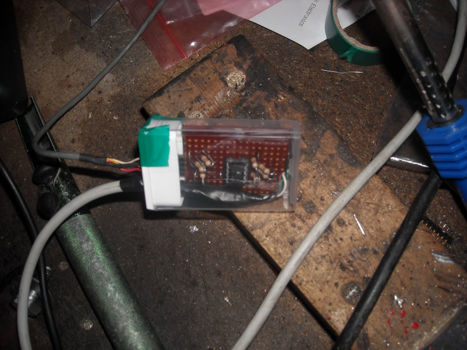
----Yet another trip to the electronics store got me a LM358 op amp. I read that these are a bit crunchy with respect to their tolerances, but my local electronic store did not have a big choice, so that was it. The LM358 is basically the same as a 741 op amp, but it is designed to work from a single rail power supply and the theory (and their claim) is that the output can go from 0v to the supply voltage. The good thing was that the pin-out was the same as the MC1458, so it swapped out no problem. I found that the range was now swinging from 0.57v to 3.6v. I tried it on the car and at 800A I was seeing 3.41v and at rest 0.58v (there's that drift). Anyway, I could work with that. I took the instrument cluster out of the car with all the new display circuit still mounted. I then added a resistor network to the proto board to set up a 0.5v offset to set the lowest level to detect. I used a 10k resistor in series with a 470 and 220 Ohm resistors making 690 Ohms. This was by trial that I found 0.5v. Now with the adjustment screw I could adjust the top level to detect and then I had my range. I then tested it out and it seemed to work fine. Next step then was to build this up on a vero board, so off to do some circuit layout designs, then build the circuit. After I had finished I mounted the new circuit in a tic-tac box (that a small mint candy box for anybody outside the UK). Tic-tac boxes have been used for many of my smaller circuits as they work on three levels; you get a box to put you circuit in, it doesn't cost much money (cheaper than a small project box), and you gets some mints to enjoy while your doing it. In the photo below you can see the new circuit in it's tic-tac box. So this circuit now sits between the sensor and the input to the "Amps x 100" display and amplifies the signal for the display to show. I tried it out with the gauge all resting on the car and the supply for the display hooked precariously directly to the battery. I ran it to 800A in sport mode (cringe mode - without the car moving) and then in economy mode that I know tops out at 500A and they displayed numbers 0 to 8 and 0 to 5 respectively. Tomorrow I will mount it all back on the car and then go for a drive to check that all is working as expected. This also means that I now have a signal and a 5v supply that I can pick up for my multi display that is next on my list of things to do. Hopefully the display connector will come soon. If it is not here by next week I shall order one from USA and ask my friend Tim to receive it and send it on. The only other 30 pin flat 0.5mm ribbon connector and breakout adapter I could find was in the USA, but although it only cost like $10, they wanted $130 to ship it to the UK. No way.
No comments:
Post a Comment