

187: Monday 25th April 2011
Today I decided to get the display control simplified so it was easy to trigger events from data sent to the graphic display. In order to do this I needed a development environment. Fortunately the usb interface came with a demo program as a stand alone program, but also as source code in various programming languages. I opted for visual basic in the vb.net domain as there was a vb2008 source code version of the demo already coded. First I had to download the Microsoft dot net framework. That took a while. Then I downloaded visual basic express 2010 from Microsoft. This is free, cool. Once I had done the installations and restarted my PC, I loaded the solution file and there I could edit the source code. This was great as the vb graphic interface development is really easy. So I dragged the bottom of the form down to make it bigger, added buttons for 'Reset', 'LCD on', 'LCD off', 'All points on', and 'All points off'. I also added a 'Toggle data' button this was so I could enable the data set in the check boxes for the digital outputs. I added a timer and set this to 1 second initially and set this to bring on the analogue voltage at the full 5v, then back to 0v after the timer had expired. This was connected to the 'E' terminal on the display to enable the data on the bus. So each button would set up the digital outputs, then bring on the analogue output for a time. I could see this working just fine, so I then set the timer to 10 milli seconds. On the board you can still see a short blip when the analogue output comes on and goes off again. I am using this just like a digital signal really, but I only had 8 digital outputs and they are used for D0..D7 input of the display. This made it very easy to send commands to the display. I installed a simple mechanical button on the prototype board to supply the hard reset voltage when pushed, so I could stop the display from locking me out. I could still only control the display to bring it on and off. I am not sure why this is right now, but I suspect the display is damaged at this point in time. I am not getting the LCD voltage from its on-board DC-DC converter, so I had to supply this using my split rail supply. I get the blue background, but no white dots. I tried the volume control, power control and resistance ratio settings amongst others as well as sending the data to the ram and nothing, nada. I shall wait till pay day and order another display and hopefully that will work. I shall also try contacting the manufacturer and getting them to supply me with a start sequence for the display and some tests to try out. I have the display data sheets (see link in side bar) for the display and the chip set on the display assembly. I have tried the sequence I believe is recommended by Epson and it does not work. This is disappointing, but nothing has been simple so far, and in the typical tradition of this whole project I have typically had 2 of everything, except the Zivan charger and Zapi controller that have worked faultlessly since the day I first tried them.

186: Sunday 24th April 2011
Started off by rewiring the usb interface as the outputs were for open collector transistor drivers and only 0.6v. There was a 5v output to each of the LEDs, so I soldered a connection to a terminal strip with screw terminals. I used a double sided sticky pad to mount this on top of the chips. I then made up a simple ribbon cable with 9 connections, one for each of the 8 outputs from the usb interface and one for ground. This had a strip of pins on the other end so I could plug it into the prototype board. I then figured out which of the bits I need to change to send a 'display on' and 'all points on' messages. The rest of the bits were wired directly high or low. I know this is really crude, but it is just to get the display up and running. I cleared up the desk with my computer on it and moved my prototype board and the display etc. over there with the usb interface. You can see this in the photo below.
 ----
----
After a thorough read of the data sheets, I found a couple of minor issues, but there was a voltage converter inside the chip that was supposed to generate a large negative voltage supply for the display. This was not working and I had the capacitors the wrong way round at one point as the two data sheet showed different polarities. I trust the Epson chip spec sheet as this is the source document. I could not get the display circuit to produce the voltage so I consulted the notes on how to connect an external voltage. I have a split rail supply on the prototype board as well as a separate 5v supply and the positive and negative rails are separately adjustable. I linked the 5v supply ground and the split rail supply ground so they had the same reference. The input voltage needed to be -9v with respect to the positive 5v supply, net effect is -4v with respect to ground. I set the negative rail to -4v and the display flicked on when I powered up. This was progress. I could see like a grid when I sent the command to switch the display on and then another very slight change when I sent the instruction to switch all points on. When I then sent the command to switch the display off, it went right off. I had to use a wired reset low to get the display back, or switch off the power supply. In the photo below you can see the display with a blue square in it. I tried sending some data and it didn't make any difference, but I had to go for dinner and finish up for the day. I have a feeling there is something else I need to do to select the right brightness level or something as I was expecting all the dots to illuminate with the 'all points on' request. I have made progress as the display is visibly responding to my requests. Step by step I will get there. I did a bit of a rewire and I shall use 2 analogue outputs from the usb interface and the 8 outputs exactly as the eight bits for the data. I only need to control the enable signal and the data or control line (A0) that are now connect to analogue outputs. I shall switch these directly from min to max to go from 0v to 5v, so they are just like the digital signals. If anybody has ideas why I am not getting any dots lit up, I'd appreciate your help.

 ----
----After a thorough read of the data sheets, I found a couple of minor issues, but there was a voltage converter inside the chip that was supposed to generate a large negative voltage supply for the display. This was not working and I had the capacitors the wrong way round at one point as the two data sheet showed different polarities. I trust the Epson chip spec sheet as this is the source document. I could not get the display circuit to produce the voltage so I consulted the notes on how to connect an external voltage. I have a split rail supply on the prototype board as well as a separate 5v supply and the positive and negative rails are separately adjustable. I linked the 5v supply ground and the split rail supply ground so they had the same reference. The input voltage needed to be -9v with respect to the positive 5v supply, net effect is -4v with respect to ground. I set the negative rail to -4v and the display flicked on when I powered up. This was progress. I could see like a grid when I sent the command to switch the display on and then another very slight change when I sent the instruction to switch all points on. When I then sent the command to switch the display off, it went right off. I had to use a wired reset low to get the display back, or switch off the power supply. In the photo below you can see the display with a blue square in it. I tried sending some data and it didn't make any difference, but I had to go for dinner and finish up for the day. I have a feeling there is something else I need to do to select the right brightness level or something as I was expecting all the dots to illuminate with the 'all points on' request. I have made progress as the display is visibly responding to my requests. Step by step I will get there. I did a bit of a rewire and I shall use 2 analogue outputs from the usb interface and the 8 outputs exactly as the eight bits for the data. I only need to control the enable signal and the data or control line (A0) that are now connect to analogue outputs. I shall switch these directly from min to max to go from 0v to 5v, so they are just like the digital signals. If anybody has ideas why I am not getting any dots lit up, I'd appreciate your help.

185: Saturday 23rd April 2011
Started work on the graphic display today. First objective was to get the display powered up and basically showing something that I have decided on. I now had the connector board from Tim in USA, cheers buddy. Had a collection of pin strips from when I was making the other displays. In the photo below you can see after I have added one row of pins to the board.
 ----
----
In this photo you see the second row of pins added. This layout is identical to IDE connectors for a floppy disk drive and I had a couple of spare ribbon cables with connectors, so that was a bonus.
 ----
----
In this photo you can see the ribbon cable connected.
 ----
----
In this photo you can see how I handled the other end of the ribbon cable that needed to connect to my prototype board. This shows one of the rows of pins that would connect to the IDE connector on the other end of the cable. As there are two rows then I needed to make two of these and offset the pins to bridge the gap on the prototype board.
 ----
----
In this photo you can see the two connectors I made between the IDE cable connector and my prototype board. I cut the cable as the next part went to a different connector and it made it easier to handle.
 ----
----
In the next photo you can see everything connected. The bits on the left of the prototype board were from another project some time ago. The display is connected to the adapter board and I put a double-sided sticky pad on it's back to stick it to the ribbon cable temporarily. This was for support as the display's own ribbon cable is like a tape. I tried just hooking up the 5v supply, and then adding the other components that were shown in the example circuit on the data sheet. I tried manually wiring the circuit data lines to send some simple instructions, but there was nothing on the display. I still need to add capacitors for the LCD driver circuits and I did not have the right values. I had the right capacitors and resistors for the voltage inputs and have added these already. I need to check what I ordered for this project and see if I should have these parts. Other wise I need to go buy them. I want to finish this up before I try anything else. I decided to just send a control instruction to turn all points on initially. That will prove that the display works. I have a usb controlled interface that I can use to set up a simple bus and send data from a PC to progress from there, then I can work out how to get a PIC chip to do the same job of the usb interface. I was impressed with the Velleman website as I bought the board about ten years ago and I have now misplaced the disk that came with it. I went to the website and within minutes I had downloaded a complete suite of example programs in many different computer languages and instructions on how to install the drivers etc. Another couple of minutes and I had the interface up and running. I now need to clear some space on the bench where my PC is and move the prototype board over to it as I don't want to trail a long usb cable across and then have to keep going backwards and forwards to see what has worked or not.

 ----
----In this photo you see the second row of pins added. This layout is identical to IDE connectors for a floppy disk drive and I had a couple of spare ribbon cables with connectors, so that was a bonus.
 ----
----In this photo you can see the ribbon cable connected.
 ----
----In this photo you can see how I handled the other end of the ribbon cable that needed to connect to my prototype board. This shows one of the rows of pins that would connect to the IDE connector on the other end of the cable. As there are two rows then I needed to make two of these and offset the pins to bridge the gap on the prototype board.
 ----
----In this photo you can see the two connectors I made between the IDE cable connector and my prototype board. I cut the cable as the next part went to a different connector and it made it easier to handle.
 ----
----In the next photo you can see everything connected. The bits on the left of the prototype board were from another project some time ago. The display is connected to the adapter board and I put a double-sided sticky pad on it's back to stick it to the ribbon cable temporarily. This was for support as the display's own ribbon cable is like a tape. I tried just hooking up the 5v supply, and then adding the other components that were shown in the example circuit on the data sheet. I tried manually wiring the circuit data lines to send some simple instructions, but there was nothing on the display. I still need to add capacitors for the LCD driver circuits and I did not have the right values. I had the right capacitors and resistors for the voltage inputs and have added these already. I need to check what I ordered for this project and see if I should have these parts. Other wise I need to go buy them. I want to finish this up before I try anything else. I decided to just send a control instruction to turn all points on initially. That will prove that the display works. I have a usb controlled interface that I can use to set up a simple bus and send data from a PC to progress from there, then I can work out how to get a PIC chip to do the same job of the usb interface. I was impressed with the Velleman website as I bought the board about ten years ago and I have now misplaced the disk that came with it. I went to the website and within minutes I had downloaded a complete suite of example programs in many different computer languages and instructions on how to install the drivers etc. Another couple of minutes and I had the interface up and running. I now need to clear some space on the bench where my PC is and move the prototype board over to it as I don't want to trail a long usb cable across and then have to keep going backwards and forwards to see what has worked or not.

184: Sunday 10th April 2011
I have had some dialogue with Tim Catellier recently and he has received a connector for me and posted it on as the company wanted $130 to ship it to UK for a $10 part. With this connector I can start the development of my graphic display. I have now had my local supplier send me the wrong connector 3 times and I have asked for a refund. This is my back-up plan and right now I am just waiting for the connector to arrive. It is a 30 way ribbon connector breakout board. This will enable me to access the very fine connections from the ribbon cable to the graphic display. It is a simple circuit board with connection spaced apart so they are easy to solder onto. I shall then connect another bigger ribbon cable to this and then to my prototype board. I can then connect up 9 or 10 switches to manually sequence through the graphic locations on the screen and program them one-at-a-time to generate the static display, then I can start coding up a PIC chip to do the same. Replacing the switches with a PIC chip shall make it possible to run the display and generate the graphics, then onto the measuring circuits. There is a load of mini projects involved in getting this display working, so I hope it will make interesting reading.
183: Friday 1st April 2011
I got my car back on the road today. Still discussing the capacity issue with my batteries, but the supplier has tested them and now they are back on the car. I am still limited to 10 miles, but this is enough to get me to work on a cold day, just. When I was fitting the batteries back I found a broken weld on the battery trays and this was causing that annoying banging noise. I drilled through and bolted it back together and I shall get round to re-welding at some point soon. I cured the vibration on the rear centre stop lamp and and fixed my rear view mirror back on the windscreen and all is back up ready to go. I now have the charger set to provide a float charge after the normal charging cycle to keep it topped up to a good level so long is the cord is connected. This means I don't lose charge while it is sitting after the charge cycle completes, cool. Seems to have the desired effect. Anyway the car is truly silent now, no knocks or bangs any more.
182: Sunday 27th March 2011
I have now had the results of the tests of batteries from the supplier and they say they are "cycled out", that's worn out to the rest of us. ---- They still have some life, so I have asked them to send them back and I will run them as long as possible. ---- Now I have the Zivan charger set to keep the batteries topped up after the charge cycle has completed. This should help. ---- I have entered my car conversion into the "Ford take charge competition", so please go to the link and click the "+1 vote" button next to my name. ---- http://apps.facebook.com/take-charge/submissions/votes/ ---- I shall get my batteries back on Tuesday and I expect to be back on the road shortly after I get them fitted.
181: Saturday 19th March 2011
Last Sunday I took out the 10 lead acid batteries and put them into my neighbours garage. They were going back to the supplier for testing. My range was down to 10 miles and I believe that it is not due to just one battery. However the battery supplier said they could not do anything until they have tested the batteries to determine their capacity and that means they will need to be cycled through charge and discharge. They also said it will take them about a week to test them, so the Probatron is now off the road. I shall call them again on Monday to see if they have the tests completed yet. Last week was not too much of a problem, as I road my bike to work on Monday (saddle sores, ouch) and got a lift on Tuesday. I was picked up on Wednesday for a drive to Germany for my work and we came back on Thursday. I borrowed my wife's Toyota Previa ("ruby") on Friday as she does not work on Fridays. I have a lift arranged again for Monday and beyond if necessary. I am looking forward to getting my batteries back and hopefully they will send me a new set soon to replace them. However my wife is not looking forward to helping put them back in the car at 50kg each.
180: Saturday 26th February 2011
I finally got the Amps x 100 gauge working right. However it only tracks with motor controller programmer test function display when I am in sport mode. I guess this is because the voltage is more chopped in economy mode. Not to worry. I am trying to simplify my controls, so I may start driving in sport mode all the time now. With the gauge I can estimate how economically I am driving. In economy mode the current is limited, so it is hard to drive too hard. This is all very well, but I have to keep flicking over to sport to pull away either that or change gear. I don't want to do either. So I can just be more careful in sport mode and maybe up the regen a bit in sport mode. This does tend to make driving a little more jerky when slowing though. I shall just go up one step on the regen.
179: Tuesday 22nd February 2011
Yesterday I fitted the instruments to the car and went for a test drive. The gauge was way too sensitive and was going all the way round to 8 (800A). I set the car to economy as I knew that it would top out at 500A. I wound the adjustment back on the display circuit and with some trials I got the display to go up to 5 and stop when pulling away in economy mode. Then I put it in sport mode and this also stopped at 5. Clearly this was no good. I wound it out again until I was reading 8, then I realised that the adjustment was just to set how much of the display is used. What I needed was a pre-scalar. I drove it like this today and I estimate I need to trim the signal down by a factor of between 3 and 4. I went to my local electronics store today and bought a multi-turn potentiometer so I can set up a potential divider on the input to the display. Using a multi-turn potentiometer means that by adjusting with a screwdriver, I can get a really fine adjustment. I shall build this onto the display circuit on Friday when I have more time in the daylight. Hopefully then this will work how I expected. I must confess that getting these gauges to work is a bit of a fine art. I shall get there soon be sure. I am looking forward to making some videos soon to show you all the different parts of this project. It is hard to show with just pictures and text.
178: Sunday 20th February 2011
After my initial failure I decided to start by eliminating all the niggly problems in order to get this amps gauge working properly. First I wasn't sure that mounting the current sensor on the cable with its insulation and some plastic tubing to put the cable in the centre of the sensor wasn't losing me some signal. I wasn't expecting the insulation or plastic pipe to affect the magnetic fields picked up, but to be sure I got a piece of 22mm copper pipe flattened one end, pushed the sensor on until it came to a gentle stop, then measured the distance from the end of the pipe to the start of the sensor. It came to 50mm. I measured 50mm from the other side of the sensor along the pipe and cut it there. I then flattened the pipe with care to get the same orientation as the other end. I drilled an 8mm hole in each end to take the mounting bolts. With this mounted on the car, I took some measurements of the output voltage. To do this I had to do something that didn't feel right, but I put my foot hard on the brake and pushed down on the throttle until the motor controller programmer test screen showed 800A (max) and read the voltage from the sensor. It was reading 2.66v. That is only 0.15v higher than the reference voltage of 2.5v. That explains why I was seeing no readings on the display before. So now I knew how the sensor was behaving I had to make another circuit to get that output into a usable form.
 ----
----
I went to my local electronics shop and stocked up on resistors and transistors. I then set about making an amplifier. My objective was to take the reference voltage and the signal voltage from the sensor and transform them into a single output with respect to 0v and feed this into the display. I would then set up the display to read properly with these new voltages. I built an NPN transistor common emitter amplifier, then another stage to invert the inverted output. I am a bit ropey on my electronics as it was about 25 years ago I first learnt all this. I eventually got to a respectable swing from 3.3v to 4.1v. This was better than the weak signal from the sensor. Next I thought that with this being possible I would try an op amp circuit to see if I could make it simpler and improve the range of the output. Another trip to the electronics store and I had an MC1458 chip that had 2 x 741 op amps on it. After a lot of fiddling about on my proto board, I got a swing from 1.96v to 4.28v. Clearly this was not ideal still. I would have liked to go much closer to 0v for the low level. I did a bit of research and found that because the 741 op amp has a split power supply for positive and negative rails and I was using just 0v and 5v as the supply, then the lowest reading I could get was about 2v (1.96 in my case). Also the highest reading would be 0.7v below the supply voltage and it was. More reading revealed that I should be using a different op amp that was designed for a single rail supply. The photo below shows my proto board with a real junk like circuit on it, but when I fired up the motor and put a load on I was getting some decent voltage levels coming back and they were predictable by design.
 ----
----
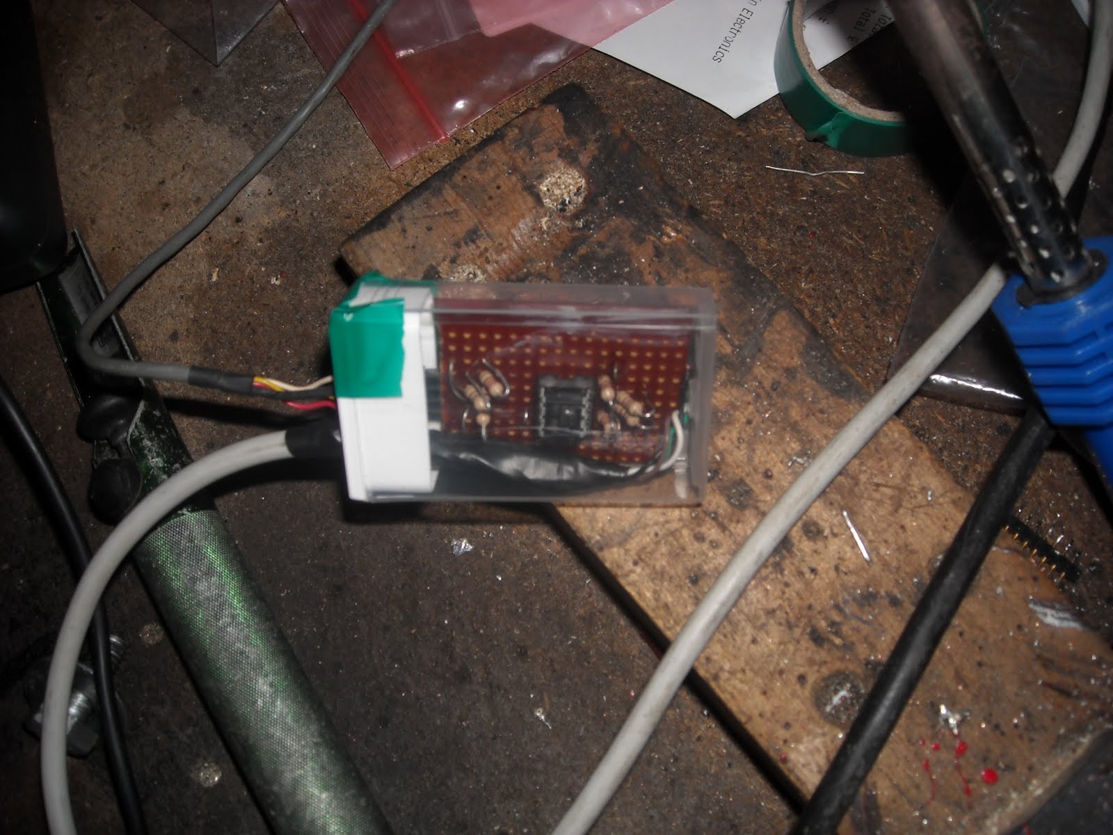
Yet another trip to the electronics store got me a LM358 op amp. I read that these are a bit crunchy with respect to their tolerances, but my local electronic store did not have a big choice, so that was it. The LM358 is basically the same as a 741 op amp, but it is designed to work from a single rail power supply and the theory (and their claim) is that the output can go from 0v to the supply voltage. The good thing was that the pin-out was the same as the MC1458, so it swapped out no problem. I found that the range was now swinging from 0.57v to 3.6v. I tried it on the car and at 800A I was seeing 3.41v and at rest 0.58v (there's that drift). Anyway, I could work with that. I took the instrument cluster out of the car with all the new display circuit still mounted. I then added a resistor network to the proto board to set up a 0.5v offset to set the lowest level to detect. I used a 10k resistor in series with a 470 and 220 Ohm resistors making 690 Ohms. This was by trial that I found 0.5v. Now with the adjustment screw I could adjust the top level to detect and then I had my range. I then tested it out and it seemed to work fine. Next step then was to build this up on a vero board, so off to do some circuit layout designs, then build the circuit. After I had finished I mounted the new circuit in a tic-tac box (that a small mint candy box for anybody outside the UK). Tic-tac boxes have been used for many of my smaller circuits as they work on three levels; you get a box to put you circuit in, it doesn't cost much money (cheaper than a small project box), and you gets some mints to enjoy while your doing it. In the photo below you can see the new circuit in it's tic-tac box. So this circuit now sits between the sensor and the input to the "Amps x 100" display and amplifies the signal for the display to show. I tried it out with the gauge all resting on the car and the supply for the display hooked precariously directly to the battery. I ran it to 800A in sport mode (cringe mode - without the car moving) and then in economy mode that I know tops out at 500A and they displayed numbers 0 to 8 and 0 to 5 respectively. Tomorrow I will mount it all back on the car and then go for a drive to check that all is working as expected. This also means that I now have a signal and a 5v supply that I can pick up for my multi display that is next on my list of things to do. Hopefully the display connector will come soon. If it is not here by next week I shall order one from USA and ask my friend Tim to receive it and send it on. The only other 30 pin flat 0.5mm ribbon connector and breakout adapter I could find was in the USA, but although it only cost like $10, they wanted $130 to ship it to the UK. No way.

 ----
----I went to my local electronics shop and stocked up on resistors and transistors. I then set about making an amplifier. My objective was to take the reference voltage and the signal voltage from the sensor and transform them into a single output with respect to 0v and feed this into the display. I would then set up the display to read properly with these new voltages. I built an NPN transistor common emitter amplifier, then another stage to invert the inverted output. I am a bit ropey on my electronics as it was about 25 years ago I first learnt all this. I eventually got to a respectable swing from 3.3v to 4.1v. This was better than the weak signal from the sensor. Next I thought that with this being possible I would try an op amp circuit to see if I could make it simpler and improve the range of the output. Another trip to the electronics store and I had an MC1458 chip that had 2 x 741 op amps on it. After a lot of fiddling about on my proto board, I got a swing from 1.96v to 4.28v. Clearly this was not ideal still. I would have liked to go much closer to 0v for the low level. I did a bit of research and found that because the 741 op amp has a split power supply for positive and negative rails and I was using just 0v and 5v as the supply, then the lowest reading I could get was about 2v (1.96 in my case). Also the highest reading would be 0.7v below the supply voltage and it was. More reading revealed that I should be using a different op amp that was designed for a single rail supply. The photo below shows my proto board with a real junk like circuit on it, but when I fired up the motor and put a load on I was getting some decent voltage levels coming back and they were predictable by design.
 ----
----Yet another trip to the electronics store got me a LM358 op amp. I read that these are a bit crunchy with respect to their tolerances, but my local electronic store did not have a big choice, so that was it. The LM358 is basically the same as a 741 op amp, but it is designed to work from a single rail power supply and the theory (and their claim) is that the output can go from 0v to the supply voltage. The good thing was that the pin-out was the same as the MC1458, so it swapped out no problem. I found that the range was now swinging from 0.57v to 3.6v. I tried it on the car and at 800A I was seeing 3.41v and at rest 0.58v (there's that drift). Anyway, I could work with that. I took the instrument cluster out of the car with all the new display circuit still mounted. I then added a resistor network to the proto board to set up a 0.5v offset to set the lowest level to detect. I used a 10k resistor in series with a 470 and 220 Ohm resistors making 690 Ohms. This was by trial that I found 0.5v. Now with the adjustment screw I could adjust the top level to detect and then I had my range. I then tested it out and it seemed to work fine. Next step then was to build this up on a vero board, so off to do some circuit layout designs, then build the circuit. After I had finished I mounted the new circuit in a tic-tac box (that a small mint candy box for anybody outside the UK). Tic-tac boxes have been used for many of my smaller circuits as they work on three levels; you get a box to put you circuit in, it doesn't cost much money (cheaper than a small project box), and you gets some mints to enjoy while your doing it. In the photo below you can see the new circuit in it's tic-tac box. So this circuit now sits between the sensor and the input to the "Amps x 100" display and amplifies the signal for the display to show. I tried it out with the gauge all resting on the car and the supply for the display hooked precariously directly to the battery. I ran it to 800A in sport mode (cringe mode - without the car moving) and then in economy mode that I know tops out at 500A and they displayed numbers 0 to 8 and 0 to 5 respectively. Tomorrow I will mount it all back on the car and then go for a drive to check that all is working as expected. This also means that I now have a signal and a 5v supply that I can pick up for my multi display that is next on my list of things to do. Hopefully the display connector will come soon. If it is not here by next week I shall order one from USA and ask my friend Tim to receive it and send it on. The only other 30 pin flat 0.5mm ribbon connector and breakout adapter I could find was in the USA, but although it only cost like $10, they wanted $130 to ship it to the UK. No way.
Subscribe to:
Posts (Atom)