I have been trying to get the display working properly and decided to mount the capacitors on the display connector board using the solder pads provided. The picture below shows the back of the board with the connections made to the display connector from the solder pads. This is not my finest bit of soldering, but the connections are good.
----The next picture shows the top of the board with the capacitors mounted. I tried the display again, and it is still not working. I am not getting the LCD voltage to drive the display. Injecting the voltage shows the blue rectangle again, but when it was aligned to the correct voltage it was all black and you could see the dots being displayed, but that was all. I suspect the capacitors may be at fault as I ran all the codes suggested by the supplier and still the LCD voltage was not right, it was reading 0.16v and should have been -4v to ground. I have now ordered some surface mount capacitors and I shall mount them when I get them. I hope that works as I am not sure what else I can do now.
----
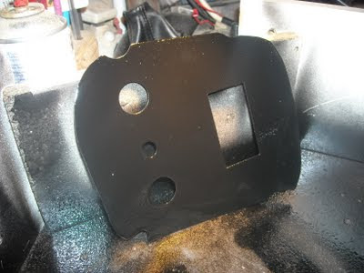
The picture below shows the plate for the controls and display to go into the centre console. I figured I would cut the rectangle for the display and then give a coat of gloss paint. I used the displayed rectangle to measure the actual display and then cut the rectangle with a hammer and chisel. The plate was so thin that any extensive filing or sawing would have distorted it dramatically. Chiselling was the best option and after I had made the first cut, I touched it up with a file to smooth the cuts out and get rid of burrs. I checked it with the display and made some minor adjustments with a file. I am not exactly sure how I am going to secure the display. I shall probably glue some spring clips to the back that the display can slide into.
----
I applied gloss black paint and allowed it to dry for a while. When the paint was still tacky I applied the graphics that I had printed off. The Forward, Reverse and PAS were made with a tape printer. I made these some time ago when I made the original panel. A quick coat of clear over the top of it all then it is ready to mount the switches etc. and fix it all back in the car. I shall come back to the display when I have it working as there is a lot to do even once I have some basic information showing on the display. The batteries will be monitored by two eight channel A to D converters through linear opto-couplers. The A to D converters shall be linked to a PIC chip through a serial port and the PIC chip will also handle the display of the levels on the screen.


No comments:
Post a Comment