203: Sunday 7th August 2011

Today I checked my email and found that my friend and enterprise colleague in the display venture had actually got my display working on command. Cool, he has put a temporary logo on the display for demonstration purposes. Next step is to rig up the battery monitor circuits so I can then work out how to display the information on this display. First I need to figure out my friends PIC chip coding..... ;o)
 ----
Had a bit of a mishap! I have been monitoring the battery voltages and found one to be a bit lower than the others, but then I noticed it had kind of melted a bit. I swapped this one out with another that I have been conditioning. It was showing better voltages, but still went down below 10v when the pack was done. This was due to severe imbalance. I have swapped this with the one running the 12v system as the demands are much lower and it may perk up yet. I did some test runs and the 12v system is holding its own still and the battery is getting conditioned too. I found another of the batteries is also reading quite low. I am hoping to get a set balance nicely soon so I can achieve some respectable mileage. I am getting a fairly reliable 10 miles with the imbalances. I hope to get this up above 15-20 miles soon. If I cannot get this right soon, then I am going to need to bottom balance the batteries and charge them all up together and hopefully this will bring them in line a bit more and also get the maximum charge in them.
 ----
While I was doing this work I noticed the batteries hissing while on charge and then I realised I had not put in the tubes for venting the gases when charging. In this photo you can see the network of pipes linked across the top at the front of the batteries.
 ----
Here is a closer photo of the tubes connecting the charging vents.

202: Friday 5th August 2011

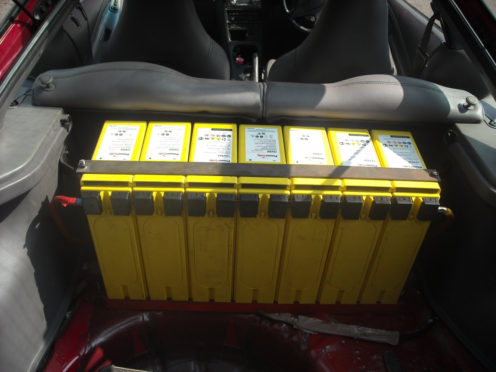
Did nothing today apart from watching movies. I am glad because it was raining and really humid. Yesterday I finished mounting the batteries in the trunk. In the photo below you can see the left side hold down bracket. Notice how there is a "dog-leg" going off the side panel where there was a fixing to hold a cargo net, that was a handy fixing point. These were also fixed to the floor of the trunk.
 ----
In this photo you can better see the hold down bracket across the top. This has a bend in it so that it applies pressure to all the batteries across the width. After the previous battery slide I was making sure these were very secure.
 ----
After having done a couple of drives in sport mode (the full 800A max) all the 12v systems started failing at around 7 miles. This was due to a failure of the main 12v battery (normal car battery). With a garage full of deep cycle batteries, it seemed like a crime to go and buy a new ordinary car battery that is not really designed for this kind of usage, so I set about figuring out how to mount another battery in the front and it just about fits. My first attempt would not allow me to shut the hood, but with some adjustments of heights and angles I was able to mount this battery firmly and make a hold down bracket too. As space was limited, I had to weld this bracket together as I could not have nuts and bolts sticking up in the air. It does make a neater job too, but you also need to get it right first time or it is a real pain re-doing. The connections were made using some cables I had laying around. I shall revisit this some time soon. After my first drive, the 12v system was low, but had not been charged after I had installed it. The second drive, after a charge saw my 12v system at a much healthier level and in both cases I did not lose any functionality, so that is another upgrade done. This cost me an extra half day that I hadn't planned for. I still need to get the front up in the air to refit the wheel arch liners and some clips on the front bumper. In the photo below, the space behind the left head lamp is where the old battery was, and the battery on its end is the new one.

201: Tuesday 2nd August 2011

Yesterday I got the batteries clamped down and connected in the front of the car.
 ----
I then added the crash impact assembly to the front.
 ----
In this photo you can see the copper strips that I used to make the connections.
 ----
Using cooper bar makes the connections neater and there is very little that can go wrong with these connections.
 ----
Today started with the bumper fitted on the top fixings only. In the photo below you can make out the side lights and indicators, but the photo does not do it justice.
 ----
In this photo just the side lights are on and the LEDs are a bit clearer.
 ----
Up close and personal, you start to get an idea of what the sidelights look like for real. I tried to take some shots at night, but the contrast was too much and the photos were either a glare or just the lights and license plate on a black background when no flash was used.
 ----
Last job of today was to mount the batteries in the rear. I still need to add some fixings to the front bumper, but I need some axle stands to jack the car up so I can get to all the fixings underneath. I borrowed these from my brother, but by the time I got round to his house I had to go back have dinner and go badminton. I did not want to start on this late, so it is a job for tomorrow. Also I have started making the hold down brackets for the rear batteries. I went for a little test drive and all the batteries slid to one side with a thud. That was a little worrying. Because I have mounted these batteries on their ends (you can do that with AGMs), I have created an enormous boot space. The rear suspension looks much more healthy now it has less weight than the previous batteries.

200: Sunday 31st July 2011

I had a refreshing week in sunny Spain on an all-inclusive holiday last week. This mainly consisted of a few walks along the beach, but mostly swimming in one of the 4 pools, sunbathing, food and drinks all free and really nice. Spent one day in a spa having Turkish, Roman, Scottish bi-thermal and aroma bi-thermal baths as well as a hot and cold jacuzzi. Feeling quite relaxed now. Came back yesterday and today I have rebuilt the battery racks for the front end of the car. In the photo you can see the batteries in position on the new rack, but the hold-down bracket is not finished yet. That is a job for tomorrow along with the rear racks. I am going to shed loads of weight and gain my boot space back. I have to remount some other brackets too for the vacuum pump and other circuits. Some of the batteries that I have brought back have lost their charge in the week they have been left and I suspect they may be FUBAR. I shall contact the recyclers and see if he has some more I can do some swapping with. He is only interested in the weight of the lead.

199: Thursday 21st July 2011

Not much to report at the moment. I have spent the last 2 weeks charging batteries up. I ended up with 2 chargers and my neighbours one died, so now I need to buy him a new one. My cheap charger is still soldiering on and I now have 14 charged batteries, at least charged enough to make them usable. Generally they are all above 12 volts now. I have decided to go with 10 batteries and not 20. I know this will give me a smaller range, but with my new battery monitor I can see a battery failing early and swap it out. In theory I should have 13 spare batteries now and if my source gets more I can swap them for a nominal fee for nice fresh ones. He is only interested in the weight of lead for recycling and not whether the battery has any usable life in it. The last batch he had in was about 100 batteries. I bought 23 with the intention of mounting 20 and having 3 spares. I think at 580kg this is just too heavy. I have also worked out a different way of mounting the batteries on their end and getting a large boot space back. There are so many advantages with having 10 instead of 20 on board. The sacrifice is range. I rarely go any large distances and I have my little Fiat if I need to. Now this is truly a hobby mule and I can do lots more upgrades in future. I am looking forward to giving the paint a freshen up as it is really faded now. I am going on holiday soon, so I shall be having a week in Spain and 1 week at home. I expect to have sparkie back running again before the end of this second week of my holiday.

197: Thursday 7th July 2011

Today my batteries arrived at 7:30am on the dot, 23 of them. Now I need to figure out how to get them all in the car. When I got home from work I popped the terminal caps off and tested them. I found only 2 batteries had any charge at all in them. They had been completely discharged. In the photo you can see I have taken the 12v charger off the car to charge these one-at-a-time. This is going to take a few weeks, so now I am asking around for more chargers. I don't want to put them on the car charger as this will deliver a large current and these need to be conditioned back up to a working voltage. However it will take about 24 hours to charge each battery and I need 18 more to get the car working. If I had 2 chargers the would take about 9 days, with 3 chargers I can do this in under 1 week. I have plenty of other jobs to be getting on with until the batteries are all charged up. I need to get to the metal supplier and get some angle section to make the new brackets. I shall mount 4 in the front and 16 in the back. I need some copper straps to make the connections as well as I only have a limited supply. I was hoping to take my car to the vehicle enthusiasts day on Thursday next week, but it would be too much of a rush job to get it done in time. As I have a "spare car" now, I don't need to rush. I want to get back onto electric drive though as it is a lot cheaper, especially if I get to charge up at work.

196: Sunday 3rd July 2011

Sorry for not blogging much lately. I have secured some more batteries from a recyclers yard and they are Enersys (Hawker) 12V92F that is 12 volts and 92 Ah for a 10 hour cycle. As they are physically quite small I have asked for 20 batteries to make 2 strings of 10 and this should give me 184Ah of capacity at 120v. They Are Lead Acid AGM technology. I shall phone tomorrow to arrange the delivery date. These were relatively cheap and I have ordered an extra 3 as reserves in case one pops and to give me more options when I run into problems.
So onto the recent upgrades:
----
The photo below shows the bracket that holds the front indicator and side light lens to the front bumper. This has damage in 2 places. I made a plate to cover the section that was cracked so it could support the fixing screw and the surrounding plastic securely and one of the sides was also cracked by the screw mounting, so I glued some washers either side so when it is fixed to the bumper it will stay together.
----
This is the Aluminium plate I made to support the mounting screw. I first made a paper template, then transferred this onto the Aluminium and then beat a curve into the shape.
----
Here the plate is glued in place and painted matt black. I used a simple spray on contact adhesive to fix this in place.
----
Next was the hood latch. I took this off and brushed the rust off using a wire brush wheel in my pillar drill and just kept moving the latch over it. I took off the some of the parts that were rusted right through. It is now just the essential part to unlatch the hood. A fresh coat of gloss black paint made it look ready to go back on. I also worked some release oil into the latch mechanism to make everything move easily and freely.
----
I spent some time with a wire brush wheel in my drill going round the area of the supporting structure behind the front bumper. This picture shows the finished area all brushed up and painted with smooth red Hammerite paint to stop the rust.
----
This photo shows the other side before any work was carried out and this side was the worst as the slam panel support was rusted right through and not attached at the bottom. This needed welding, so it was left until the welding was done.
----
Next I moved onto the indicator and side light clusters. The photo shows a row of ultra bright LEDS all glued in place ready for wiring up. Originally I did some tests to try to run the LEDs in groups in series to eliminate the volt drop resistors. I found a group of 7 LEDs worked well an were nice and bright. However when I connected them and tried it on the car, they would not work because the voltage was slightly lower. This made them voltage intolerant. I had all the resistors I needed to have a single resistor for each LED, but inside the cluster this would generate too much heat as each resistor is essentially wasting 10 of the 12 volts available so the LED can work and this worked out nearly 0.25 Watts for each LED. I know this doesn't sound much, but I was planning to have 63 Ultra Bright Amber LEDs for the indicators and 63 Ultra Bright White LEDs for the side lights. That makes 126 LEDs at 0.25W or 32 Watts of heat.
----
Here the lens is separated from the mirrored part. I found that if I had 3 LEDs in series with a single volt drop resistor, then this was 1/3 of the number of resistors wasting energy and they are all doing this at half the voltage, so 1/6 of the power or about 5 Watts and that is o.k.
----
Here you can see the Amber LEDs all lit up in the dark. I shall still keep the bulb as this is brighter and the fault detection does not "see" the LEDs load properly, so with the bulb everything works fine.
----
Making up all these groups of 3 LEDs in series was much neater if I made them up before gluing them to the plastic lens. So I made a jig to position the LEDS so they could have the connections trimmed folded and soldered together nice and neat in 3s.
----
If you can make out in the photo below there are two long rows of LEDs (white and amber) mounted on the lens. This was a real labour of love as it took absolutely ages and was very frustrating as one little slip when tested them would damage a group of 3 LEDs, then I had to chisel them off the lens and make a new set of 3. They were all held on with super glue (cyanolacrylate).
 ----
Finally today my friend took Sparky away and welded the front panel. I can now finish brushing up the rusty bits and painting before the bumper goes back on with it's new funky LED lights, cool.
 ----
The same friend has also sorted me out another car to use while I am completing all the upgrades and waiting for batteries. I had another run-around when I first started this project in March 2009, but I sold it when I got Sparky on the road. This was a mistake as the Lead Acid batteries don't last very long so while I save up for Lithium batteries I shall keep getting recycled UPS batteries for a relatively cheap price and if I am stuck then I have my run-around to get me out of a fix. I feel much happier and my wife is too as I can stop nicking her car now. The Toyota Previa is quite a big car as a run-around and more expensive. This car is a 1998 Fiat Punto 1.2L Petrol and Manual transmission. Very clean and cheap to buy and run.
----
I shall not leave it so long between blogs now. I just was a bit short of cash and I ran out of batteries in my camera and could not power it up to get the photos off.

195: Sunday 29th May 2011

When I win the lottery, I want to be able to get the Probatron a fresh coat of flashy paint and some scissor action door hinges. If I do win the lottery then I will make it into a convertible as well. An electric Ford Probe convertible with flippy up doors and a flashy paint, how cool is that? Until then, I can just try and scrape off some rust and make good everything underneath the bumpers. Starting with the front. I found a couple of bonuses in removing the front bumper, I could remove the redundant coolant filler tank and PAS cooler pipe that was all corroded. so that another approx 1kg off the weight. The picture below shows the front end stripped down and rusty.
 ----
Hopefully the next time I report on this it will be after I have dug all the rust off, brushed it all back and applied rust inhibitor, then I can start painting it and applying protection coats, then I can fit the bumper back on. I am contemplating changing the bumpers to some funky body kit as there are some rather smart ones out there for the Probe. I shall also have a go at updating the lights to include some LED strip instead of the normal side lights. The lights come apart fairly easily, so this should be fairly straight forward.

194: 28th May 2011

I have fitted the centre console back in the car, but I cannot remember if the PAS switch was "on" when I took it out of the old panel. It does not matter as there are no markings to say which is on and off. I know that I set it up so when it is off, the switch is illuminated. This is not a problem now as I don't have a gear lever in the way any more. It all went back together with no real problems. The only change I had to make was to the wiring between the FWD/REV switch and the stop button as they were no longer right next to each other, so I had to make a longer wire between them. Not really a problem. The photo below shows the view from the Drivers door.
----
The next photo below shows the view from the passenger side.

193: Friday 27th May 2011

I went and got some stock from the stationary section of my local supermarket to make up the centre console panel to mount the display and other controls. My local supermarket is huge and has everything, so I came back with a selection of coloured card, some spray glue, some glue sticks, and I had ordered some acetate sheets from eBay that came the other day. I took the panel that I had spent ages trying to paint and run a sander over it and took it all off. I didn't strip it right back, which worked to my advantage as it gave me a good keyed surface to stick to. I sprayed glue on the metal and let it go tacky for about 30 seconds, then applied a sheet of black card. I let it set for a few minutes, then trimmed it round with a craft knife. I modified the design I had before for the panel and made a reverse stripe that I printed using a laser printer onto red card. I cut out the stripe and sprayed the back of it with glue. After it had dried for about 30 seconds I carefully stuck it on top of the black card. I then got a sheet of white paper and marked the outline of the panel on it. I cut it out with scissors and then offered it up to the centre console with the metal panel behind it. Using a pencil I marked the edge of the hole in the centre console onto the white template. I took the template and cut just outside the line I had made, but I left it right up to the edges where the fixing points were so I could align it correctly on top of the plate again. I positioned the sheet and taped it through the holes to the back of the sheet to hold it in position and then sprayed glue over giving a layer of glue on the edge of the plate after I had peeled away the white template. I let this dry for 30 seconds and then applied a sheet of acetate and gripped it on all the way round where there was glue, being careful not to touch the centre as I had some of the glue on my hands by then. I then trimmed this up and cut out the holes for the controls, but I left the sheet over where the display will go as this offers protection from getting marked. Another advantage of this approach is that I can just "re-skin" it with another sheet of acetate if it gets damaged in future. The picture below shows the console with 2 of the controls loose fitted. I shall put this all back in the car tomorrow probably.